EasyManuals Logo

Nidec Digistart D3 User Manual

Nidec Digistart D3
112 pages
To Next Page IconTo Next Page
To Previous Page IconTo Previous Page
Page #100 background imageLoading...
Page #100 background image
100 Digistart D3: User Guide
Issue: G
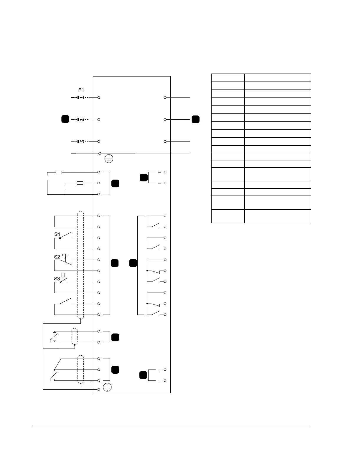
10.4 Auxiliary Trip Circuit
In normal operation the Digistart D3 is controlled via a remote two-wire signal (terminals DI2, +24V).
Input A (terminals DI4, +24V) is connected to an external trip circuit (such as a low pressure alarm switch for a
pumping system). When the external circuit activates, the soft starter trips, which stops the motor.
6/T3
2/T1
4/T2
5/L3
3/L2
1/L1
RLC3
COM3
COM1
RLO1
+24V
0V
RLO2
COM2
RLO3
AO1
0V
COM4
RLC4
RLO4
TH2
TH1
DI2
+24V
DI3
+24V
DI4
+24V
+24V
+24V
DI5
PT4
PT5
PT3
CSR
CSL
CSH
DI1
E
E
110-210VAC
+10%
-15%
220-440VAC
+10%
-15%
7
6
4
3
2
1
8
9
5
08536.B
1
Control voltage
2
Remote control inputs
3
Motor thermistor input
4
RTD/PT100 input
5
24 VDC output
6
Relay outputs
7
Analog output
8
Three-phase supply
9
Motor terminals
S1
Start/stop contact
S2
Reset contact
S3
Auxiliary trip contact
F1
Semiconductor fuses
(optional)
COM1, RLO1
Relay output A
COM2, RLO2
Run relay output
COM3,
RLC3, RLO3
Relay output B
COM4,
RLC4, RLO4
Relay output C

Table of Contents

Questions and Answers:

Question and Answer IconNeed help?

Do you have a question about the Nidec Digistart D3 and is the answer not in the manual?

Nidec Digistart D3 Specifications

General IconGeneral
BrandNidec
ModelDigistart D3
CategoryController
LanguageEnglish

Related product manuals