Digistart D3: User Guide 97
Issue: G
10 Application Examples
A selection of Application Notes are available describing advanced installation or configuration of the Digistart D3 for
situations with specific performance requirements. Application notes are available for situations including brake and
jog operation, pumping and advanced protection options.
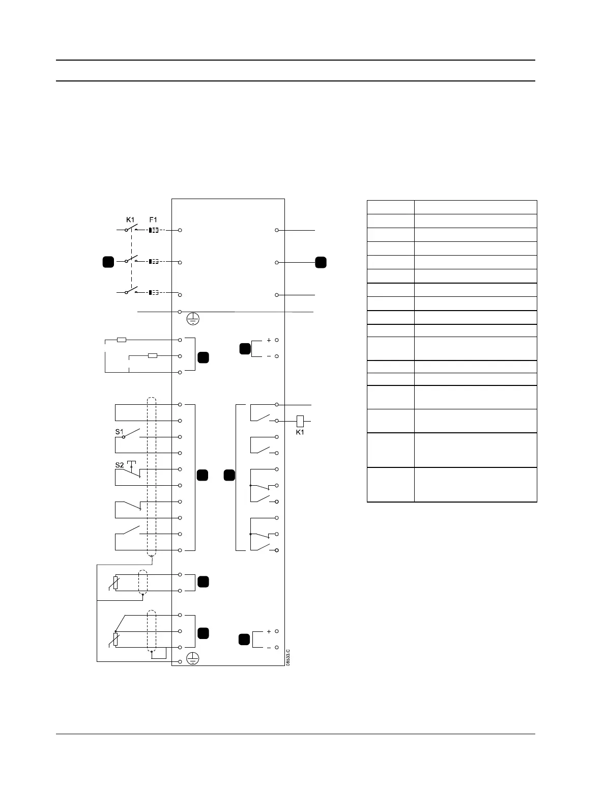
10.1 Installation with Main Contactor
The Digistart D3 is installed with a main contactor (AC3 rated). Control voltage must be supplied from the input side
of the contactor.
The main contactor is controlled by the Digistart D3 Main Contactor output, which by default is assigned to Output
Relay A (terminals COM1, RLO1).
RLC3
COM3
COM1
RLO1
+24V
0V
RLO2
COM2
RLO3
AO1
0V
COM4
RLC4
RLO4
TH2
TH1
DI2
+24V
DI3
+24V
DI4
+24V
+24V
+24V
DI5
PT4
PT5
PT3
CSR
CSL
CSH
DI1
E
110-210VAC
+10%
-15%
220-440VAC
+10%
-15%
6/T3
2/T1
4/T2
5/L3
3/L2
1/L1
E
7
6
4
3
2
1
8
9
5
Semiconductor fuses
(optional)
RLC3,
RLC4,
Parameter settings:
• Pr 4A Relay A Action
• Select 'Main Contactor' - assigns the Main Contactor function to Relay Output A (default setting)