Safety information Product information Mechanical installation Electrical installation Multi axis system design Technical data
110 Digitax HD M75X Series Installation and Technical Guide
Issue Number: 5
6.1.26 Electromagnetic compatibility (EMC)
This is a summary of the EMC performance of the drive. For full details, refer to the EMC Data Sheet which can be obtained from the supplier of the
drive.
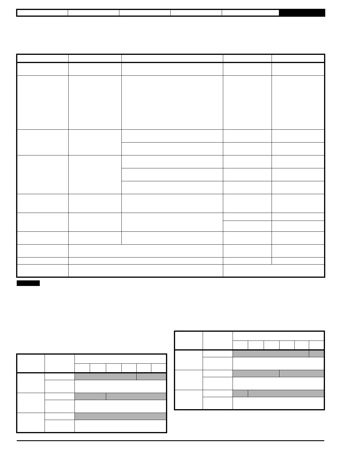
Table 6-26 Immunity compliance
1. Applies to ports where connections may exceed 30 m length. Special provisions may be required in some cases - refer to the Digitax HD M75X
EMC data sheet which can be obtained from supplier of the drive.
2. Not all parts can be tested using the IEC 61000-4-5 standard. Where cabling between external power supplies and the drives are 10 m the power
supply itself should provide sufficient surge protection.
Emission
The drive contains an in-built filter for basic emission control. An
additional optional external filter provides further reduction of emission.
The requirements of the following standards are met, depending on the
motor cable length and switching frequency.
Table 6-27 Frame 1 three phase emission compliance (200 V drives)
Table 6-28 Frame 2 three phase emission compliance (200 V drives)
Standard Type of immunity Test specification Application Level
IEC 61000-4-2 Electrostatic discharge
6 kV contact discharge
8 kV air discharge
Module
enclosure
Level 3
(industrial)
IEC 61000-4-3
Radio frequency
radiated field
Prior to modulation:
10 V/m 80 - 1000 MHz
3 V/m 1.4 - 2.0 GHz
1 V/m 2.0 - 2.7 GHz
80 % AM (1 kHz) modulation
Safe Torque Off (STO) tested to :
20 V/m 80 – 1000 MHz
6 V/m 1.4 - 2.0 GHz
3 V/m 2.0 - 2.7 GHz
Module
enclosure
Level 3
(industrial)
IEC 61000-4-4 Fast transient burst
5/50 ns 2 kV transient at 5 kHz/100 kHz
repetition frequency via coupling clamp
Control lines
Level 4
(industrial harsh)
5/50 ns, 2 kV transient at 5 kHz/100 kHz
repetition frequency by direct injection
Power lines
Level 3
(industrial)
IEC 61000-4-5 Surges
Common mode 4 kV
1.2/50 s wave shape
AC supply lines: line
to earth
Level 4
Differential mode 2 kV
AC supply lines: line
to line
Level 3
Common mode 1 kV
Control lines & DC
supply lines
(Notes:1 & 2)
IEC 61000-4-6
Conducted radio
frequency
10 V prior to modulation
0.15 - 80 MHz
80 % AM (1 kHz) modulation
Control and power
lines
Level 3
(industrial)
IEC 61000-4-11
Voltage dips, short
interruptions &
variations
All durations
AC supply lines
DC supply lines
IEC 61000-4-8
Power frequency
magnetic field
1700 A/m RMS. 2400 A/m peak (2.1 mT RMS
3 mT peak) continuous at 50 Hz
Module
enclosure
Exceeds level 5
IEC 61000-6-1
Generic immunity standard for the residential, commercial and light -
industrial environment
Complies
IEC 61000-6-2 Generic immunity standard for the industrial environment Complies
IEC 61800-3
Product standard for adjustable speed power drive systems (immunity
requirements)
Meets immunity requirements for first and
second environments
Switching
frequency
EMC filter
Frame 1
3 m 5 m 10 m 15 m 20 m 50 m
3 kHz
Internal
C3 C4
Internal and
external
C1
8 kHz
Internal
C3 C4
Internal and
external
C1
16 kHz
Internal
C4
Internal and
external
C1
Switching
frequency
EMC filter
Frame 2
3 m 5 m 10 m 15 m 20 m 50 m
3 kHz
Internal
C3 C4
Internal and
external
C1
8 kHz
Internal
C3 C4
Internal and
external
C1
16 kHz
Internal
C3 C4
Internal and
external
C2