Safety information Product information Mechanical installation Electrical installation Multi axis system design Technical data
Digitax HD M75X Series Installation and Technical Guide 27
Issue Number: 5
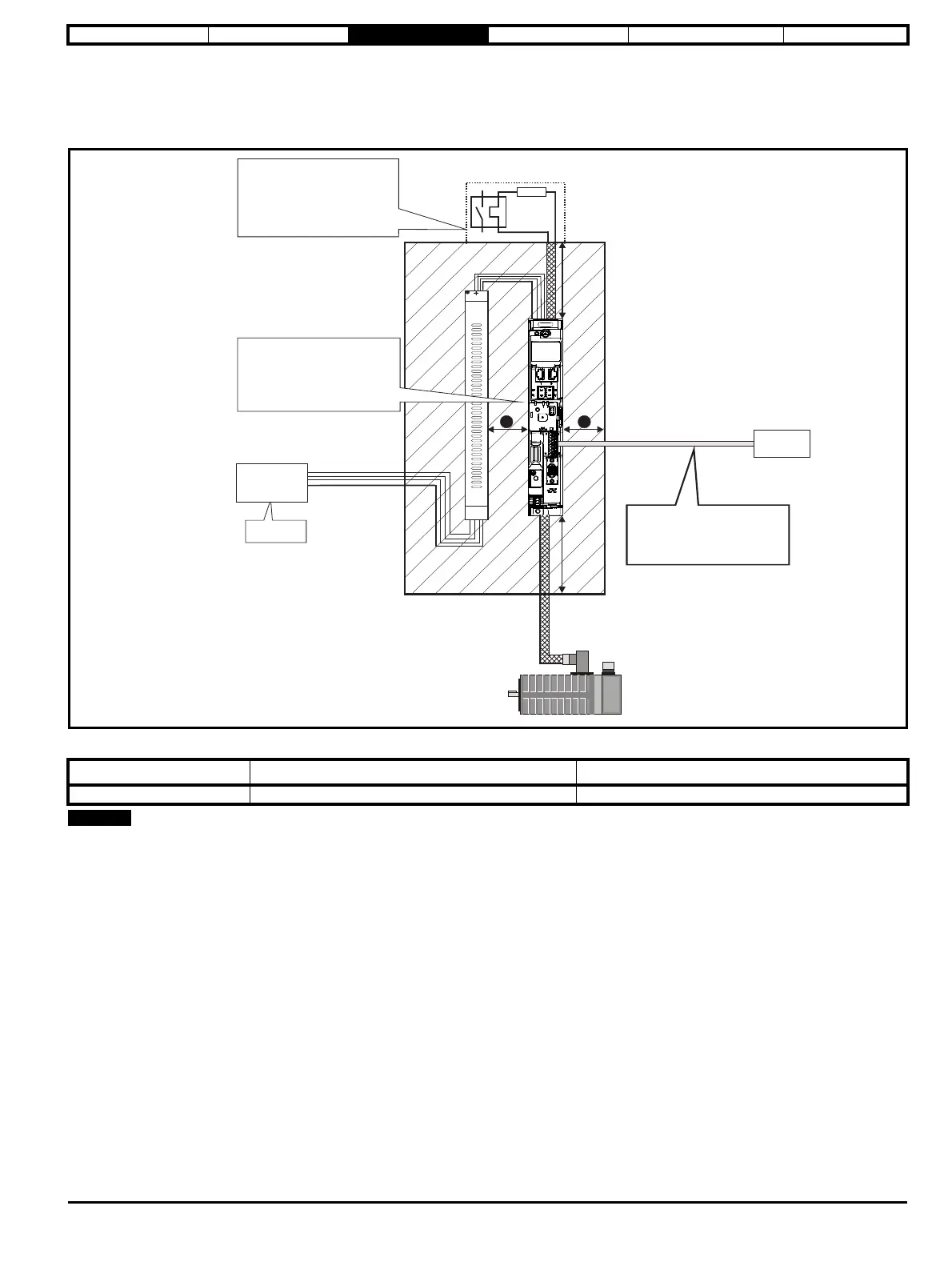
3.8 Enclosure layout
Please observe the clearances in the diagram below taking into account any appropriate notes for other devices / auxiliary equipment when planning
the installation.
Figure 3-14 Enclosure layout
Table 3-1 Spacing required between drive / enclosure and drive / EMC filter
Drives may be mounted side by side (0 mm).
Drive Size Spacing between EMC filter and drive (A) Spacing between enclosure side wall and drive (B)
All 0 mm (0.00 in) 10 mm (0.39 in)
³100 mm
(4 in)
Enclosure
³100mm
(4in)
Optional braking resistor and overload
Locate as
Locate optional braking
resistor external to
cubicle (preferably near to or
on top of the cubicle).
Locate the overload protection
device as required
B
B
Ensure minimum clearances
are maintained for the drive
and external EMC filter. Forced
or convection air-flow must not
be restricted by any object or
cabling
Locate as
required
AC supply
contactor and
fuses or MCB
A
External
controller
Signal cables
Plan for all signal cables
to be routed at least
300 mm (12 in) from the
drive and any power cable