Safety information Product information Mechanical installation Electrical installation Multi axis system design Technical data
70 Digitax HD M75X Series Installation and Technical Guide
Issue Number: 5
Figure 4-19 Sensitive signal circuit clearance
Avoid placing sensitive signal circuits in a zone 300 mm (12 in) in the area immediately surrounding the power module. Ensure good EMC grounding.
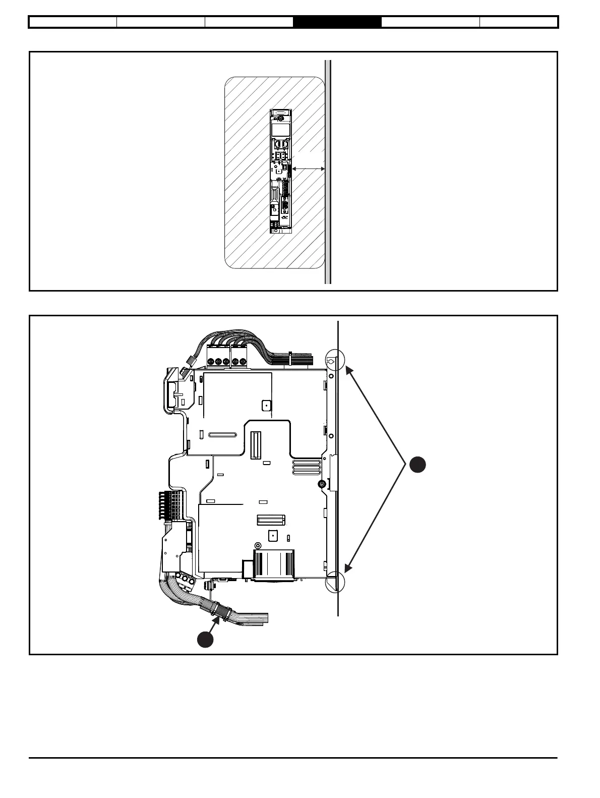
Figure 4-20 Grounding the drive, motor cable shield and filter
1. Ensure direct metal contact at drive mounting points (any paint must be removed).
2. Motor cable shield (unbroken) electrically connected to and held in place by cable screen bracket.
Connect the shield of the motor cable to the ground terminal of the motor frame using a link that is as short as possible and not exceeding 50 mm
(2 in) long.
Sensitive
signal
cable
³300 mm
(12 in)