Safety information Product information Mechanical installation Electrical installation Multi axis system design Technical data
Digitax HD M75X Series Installation and Technical Guide 79
Issue Number: 5
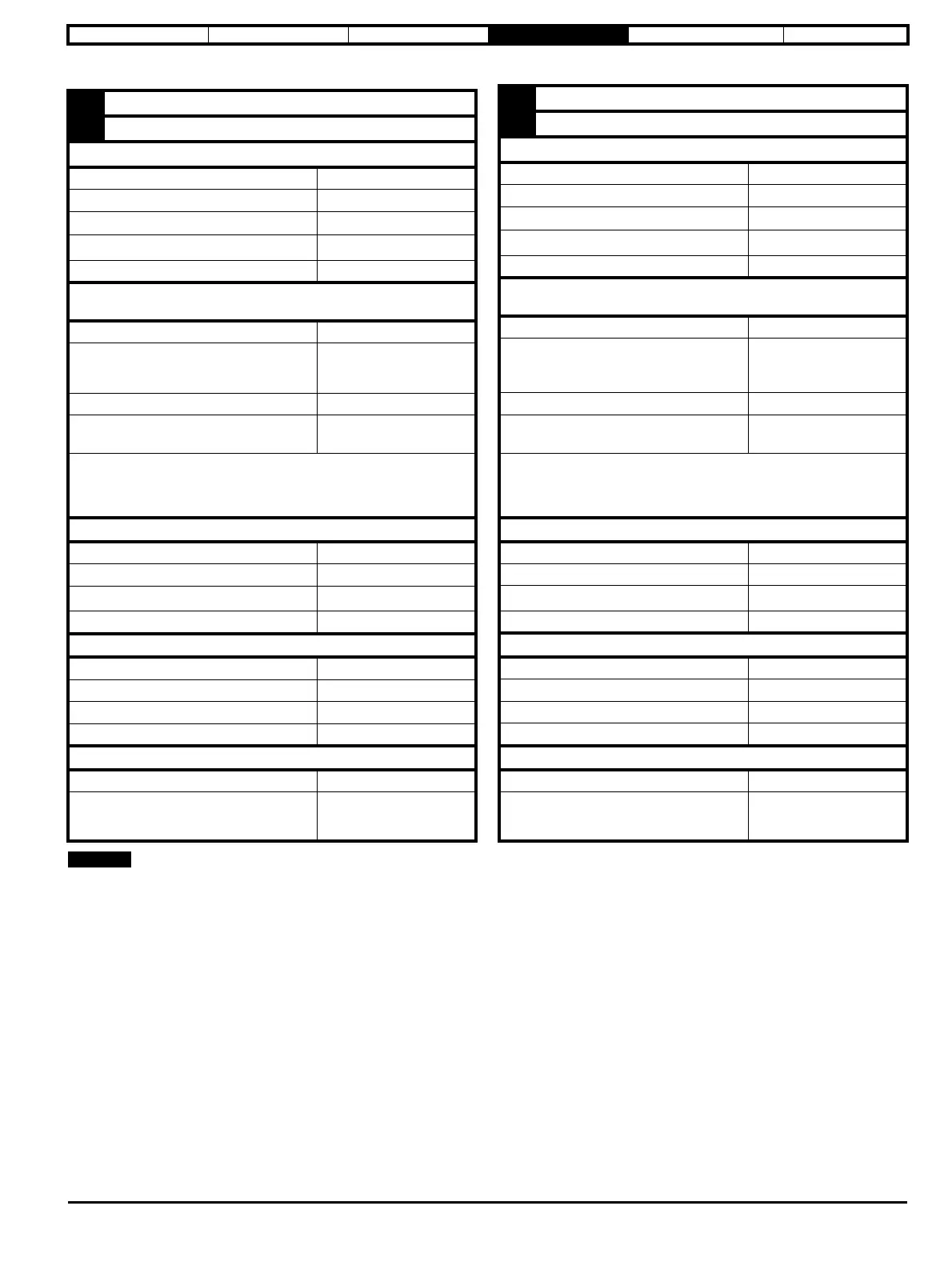
4.12.4 Position feedback terminal specifications
The position feedback input will accept 5 V TTL differential signals.
1
A,F, Cosref, Data, Cos H
2
A\,F\ Cosref\, Data\, Cos L
AB (0), FD (1), FR (2), AB Servo (3), FD Servo(4), FR Servo (5
)
Type EIA-485 differential receivers
Maximum input frequency 500 kHz
Line loading
2 unit loads
Line termination components
120
(switchable)
Working common mode range –7 V to +12 V
SC Hiperface (7), SC EnDat (9), SC SSI (11), SC Servo (12),
SC SC (15), SC BiSS (17)
Type Differential voltage
Maximum Signal level
1.25 V peak to peak (sin with
regard to sinref and cos with
regard to cosref)
Maximum input frequency See Table 4-21
Maximum applied differential voltage and
common mode voltage range
4 V
Resolution: The sine wave frequency can be up to 500 kHz but the resolution is
reduced at high frequency. Table 4-21 shows the number of bits of interpolated
information at different frequencies and with different voltage levels at the drive
encoder port
EnDat (8), SSI (10), BiSS (13)
Type EIA-485 differential receivers
Maximum input frequency 4 MHz
Line termination components
120
(switchable)
Working common mode range –7 V to +12 V
Resolver (14)
Type 2 Vrms sinusoidal signal
Operating Frequency 6 - 8 kHz
Input voltage 0.6 Vrms
Minimum impedance
85
Common to All
Absolute maximum applied voltage relative to 0V
-9 V to 14 V
Maximum
differential voltage between terminals
(with termination resistors enabled)
6 V
3
B, D, R Sinref, Clock, Sin H
4
B\, D\, R\, Sinref\, Clock\, Sin L
AB (0), FD (1), FR (2), AB Servo (3), FD Servo(4), FR Servo (5
)
Type EIA-485 differential receivers
Maximum input frequency 500 kHz
Line loading
2 unit loads
Line termination components
120
(switchable)
Working common mode range –7 V to +12 V
SC Hiperface (7), SC EnDat (9), SC SSI (11), SC Servo (12),
SC SC (15), SC BiSS (17)
Type Differential voltage
Maximum Signal level
1.25 V peak to peak (sin with
regard to sinref and cos with
regard to cosref)
Maximum input frequency See Table 4-21
Maximum applied differential voltage and
common mode voltage range
4 V
Resolution: The sine wave frequency can be up to 500 kHz but the resolution is
reduced at high frequency. Table 4-21 shows the number of bits of interpolated
information at different frequencies and with different voltage levels at the drive
encoder port
EnDat (8), SSI (10), BiSS (13)
Type EIA-485 differential receivers
Maximum input frequency 4 MHz
Line termination components
120
(switchable)
Working common mode range –7 V to +12 V
Resolver (14)
Type 2 Vrms sinusoidal signal
Operating Frequency 6 – 8 kHz
Input voltage 0.6 Vrms
Minimum impedance
85
Common to All
Absolute maximum applied voltage relative to 0V -9 V to 14 V
Maximum
differential voltage between terminals
(with termination resistors enabled)
6 V