27 | Kato Engineering, Inc.
of field excitation voltage and also the location of the ground fault. Thus an alarm based on the
leakage current only would result in a ground fault alarm threshold that varies significantly with field
voltage/fault location. Monitoring the actual field leakage resistance eliminates this variation
resulting in an alarm point, which is much more predictable, thus reducing the possibility of
premature or intermittent ground fault alarms.
The ground detector transmitter sends ground fault leakage resistance parameter measurements to
the stationary receiver. When the generator field to ground fault leakage resistance falls below a
programmable threshold (nominally 10KΩ), the receiver activates the GROUND FAULT alarm
signal. The receiver performs the ground resistance calculations based on the data it receives from
the rotor monitor/transmitter.
The rotating transmitter monitors the leakage to ground resistance by injecting a one-to-two pulse-
per-second square wave between the shaft (ground) and the negative rotating field lead. The
connection of the ground fault detection circuits of the transmitter to ground is via a resistor, two
diodes, and terminals. The voltage rating of the diodes is sufficient to withstand a 500 Volt leakage
test (“megger”) of the rotor with a 2 X safety factor. Incorrect polarization of the “megger” will result
in an indication of excessive leakage but will not damage the ground detector circuitry. The detector
connects to both the positive and the negative field leads. The leakage current that flows during
each half of the square wave is measured by monitoring the voltage across the sensing resistor.
This sensed voltage plus the field voltage is sampled by a microprocessor.
The digitized data is transmitted in “packets” at a carrier frequency of approximately 418 MHz to the
receiver. A dipole antenna is used to transmit this signal to the receiver. The data “packets” are of
short duration so the same data will be transmitted several times during each transmit cycle.
The receiver loop antenna is the inductive power loop. This antenna powers the transmitter via an
RF link thereby allowing the transmitter to be operational at all speeds with or without excitation.
Power for the rotating element is supplied through this inductive loop antenna. This power
transmission antenna consists of two series-connected loops, spatially parallel, circumferentially
located just outside the path followed by the rotating element. The frequency of this power is
approximately 100 KHz.
The loops are secured somewhat away from the frame steel on insulated standoffs at eight equally
spaced locations. The two parallel loops are necessary because the rotor assembly can move up to
approximately one inch axially between cold and full operating temperature. The dual loop system
allows for a larger axial misalignment. Tuning of the power transmitter (in the stationary element) is
not required. A dynamic tuning process is being used in this application, using a Digital Signal
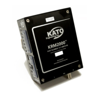
Processor for control. The KRM2000
TM
receiver currently has the capability of tuning utilizing two
different methods. The first and default method is to continuously step the loop frequency to
maintain the maximum loop voltage, with the step size being programmable. The second method is
to do a sweep and hold. The frequency is swept from 95 to 130 kHz and the peak voltage is
recorded during that sweep. The loop frequency is then set based on the peak value found through
the sweep. The loop is swept from 3.5 kHz below resonant frequency to 3.5 kHz above resonant
frequency every 10 seconds to account for variations in resonant frequency. Both methods help
optimize the transmission efficiency to the loop and help account for loop mis-alignment, which
ultimately means more power available to the rotating transmitter.