NE200/300 Series Drive User Manual
Chapter 3 Wiring of Drive 49
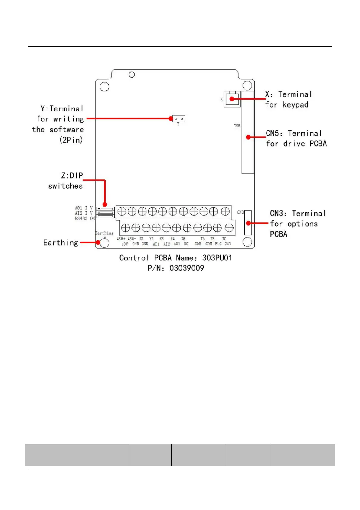
3.8.2 NE300 Control board schematic drawing
Fig.3-28 Control board schematic drawing
Note: X, Y and Z indicates the terminal, there are no the printing symbols.
There are no printing symbols on 303PU01.
X: Terminal for keypad
Y: Terminal for writing the software. (2Pin terminal)
Z: DIP switches
CN3: Terminals 1 for options PCBA
CN5: Terminal for drive PCBA
Earthing: Earthing point of control PCBA
3.8.2.1 NE300 Control circuit periphery accessories selection
Terminal codes
Terminal
screw
Tightening
torque(N·m)
Wire
Spec.mm
2
Type of Wire