R-4104.A
DISASSEMBL Y PROCEDURE
3.
Arm
Unit
4) After removing bottom plate @
from
the base,
and
releasing
'@
x4,
take off ann
CD
from
base
body @ . (Fig. 29).
5) Releasing screws @ and @ (LABOPHOT: @B
and
@
),
draw
out
rack
®
together with
washers
@ - @ toward
the
base.
(Fig.
29).
6) Forcibly draw out roller
race
(male) toward
the
base.
(Fig.
31).
7) Releasing
screws
<@ x
J,
remove
roller
race
(female)
@.
(This@
being cemented
to
main
body
CD
by
e@,
strike
it
with
a wooden hammer).
In
this case,
the
lefthand
(viewed
from
the user)
race
being
to
serve
as
fiducial in
reassembling,
remove
only
the
righthand one.
At
this time, cylindrical roller @ and
re
tainer @
will
separa te.
<
The
disassembly described below should
be
attempted only
by
an
expert >
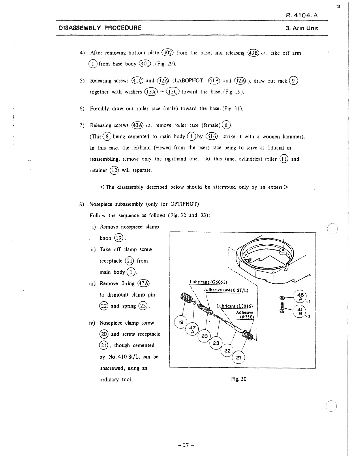
8) Nosepiece subassembly (only
for
OPTIPHOT)
Follow the sequence
as
follows
(Fig. 32 and 33):
i)
Remove
nosepiece clamp
knob
@.
ii)
Take off clamp screw
receptacle
@
from
main
body
(D.
Lubricant (G605
3)
ili)
Remove
E-ring
@
to dismount clamp
pin
@ and spring @ .
Adhesive
(#410 ST/L)
iv)
Nosepiece clamp screw
@ and screw receptacle
@, though cemented
by
No.
410 St/L, can
be
unscrewed,
using
an
ordinary tool.
Fig. 30
-
27
-
 Loading...