Control System - Battery Version 22Service Manual – SC450
Control System - Battery Version
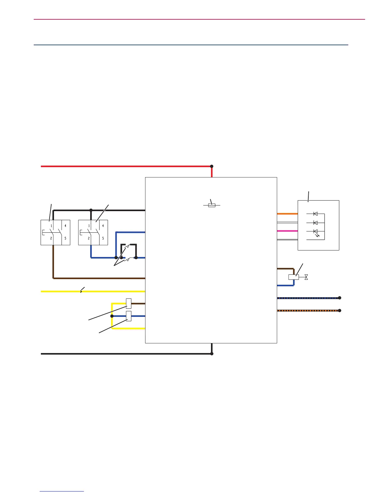
Functional Description
The function control is performed directly by the brush switch (SW1), the vacuum system switch (SW2) and
the brush activation push-buttons (SW3 with SW4).
The switches (SW1) and (SW2) power the function electronic board (EB1).
The control circuits are protected by the fuse (F3) on the function electronic board (EB1).
The battery voltage is shown on the electronic board LED (EB2).
Wiring Diagram
J1.1 - Switch power supply
J1.1
J1.2
J1.3
J1.4
J2.6 - Power supply (-)
J2.7 - Power supply (+)
J1.6 - Green LED -
J1.5 - Yellow LED -
J1.4 - Red LED -
J1.7 - Common LED +
J3.1 - Solenoid valve (+)
J3.2 - Solenoid valve (-)
J2.5 - Brush motor current detection (+)
J2.4 - Brush motor current detection (-)
J1.8 - Brush system Switch
J1.2 - Brush switch activation
J1.3 - Vacuum system switch
F1 - Battery charger power supply
J2.3 - Vacuum system relay power supply
J2.2 - Brush relay power supply
J2.1 - Relay power supply
VACUUM SYSTEM
SWITCH (SW2)
BRUSH
SWITCH (SW1)
BRUSH ACTIVATION
PUSH-BUTTONS (SW3 with SW4)
CONNECTOR (C2)
VACUUM SYSTEM
MOTOR RELAY (ES2)
BRUSH MOTOR
ELECTROMAGNETIC
SWITCH (ES1)
SOLENOID VALVE AND
ELECTRONIC BOARD FUSE (F3)
FUNCTION
ELECTRONIC BOARD (EB1)
ELECTRONIC BOARD
LED (EB2)
SOLUTION SOLENOID
VALVE (EV1)
P200006
 Loading...