Scrub System, Disc - Battery Version 62Service Manual – SC450
Scrub System, Disc - Battery Version
Functional Description
The disc brush system can be started by the operator.
The disc brush turn counter-clockwise.
The brush system, when turning, cleans/washes the
oor surface and assist machine forward movement.
The deck, where brushes suitable for cleaning the
particular type of oor are installed, is the main part
of the brush system. The brush deck is xed and in-
tegrated in the machine with a support plate. On the
support plate, there are two handwheels to adjust the
machine straight forward movement and speed.
The brush working pressure is functional to the ma-
chine designed balance.
The brush motor (M1) is supplied by the electromag-
netic switch (ES1) which is driven by the function
electronic board (EB1) when the switches (SW1) and
(SW3 with SW4) are closed. The circuit is protected
by the brush fuse (F1) and by the electronic protection
system described in the Function Electronic Board
Specications, in the Control System chapter.
The system, once activated, uses the solution coming
form the solution system, to wash the oor.
In case of brush motor overload, a safety system stops
the brushes after about one minute of continuous
overload. The overload is shown by the three battery
warning LEDs ashing simultaneously.
The overload is detected by monitoring the current
ow on the motor. The current is measured by check-
ing the voltage drop through the brush fuse (F1). If
the voltage drop is higher than 40 mV, the 3 battery
LEDs ash simultaneously and, if the overload per-
sists, the motor stops after a variable delay, depend-
ing on the overload amount.
To start scrubbing again after a brush stop due to
overload, turn off and then on the machine with the
brush switch (SW1).
To work properly, the brush motor needs the follow-
ing:
• Brush switch (SW1) turned on
• Push-button (SW3) pressed
• Charged battery (the red LED must not be ash-
ing).
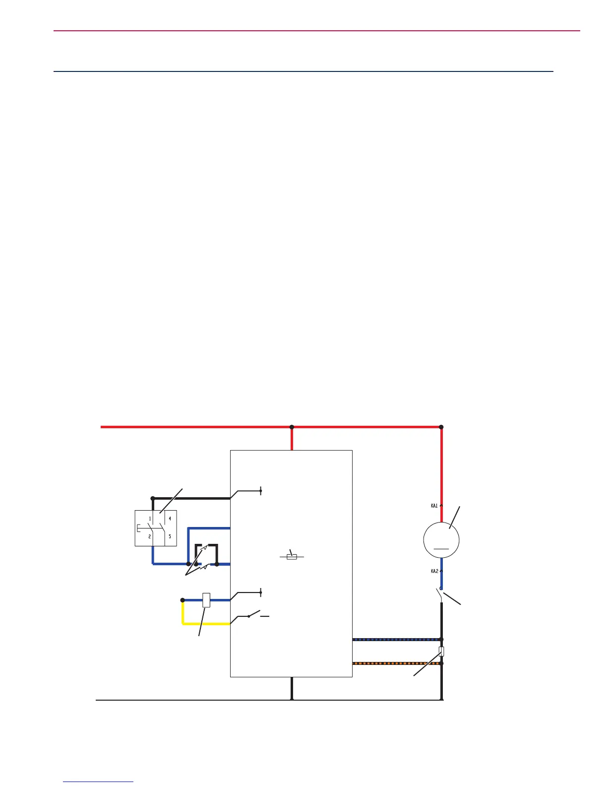
Wiring Diagram
FUNCTION ELECTRONIC
BOARD (EB1)
BRUSH MOTOR
ELECTROMAGNETIC
SWITCH (ES1)
BRUSH MOTOR
SWITCH (ES1)
BRUSH MOTOR
FUSE (F1)
SOLENOID VALVE AND
ELECTRONIC BOARD FUSE (F3)
BRUSH
MOTOR (M1)
BRUSH
SWITCH (SW1)
BRUSH ACTIVATION
PUSH-BUTTONS (SW3) (SW4)
J1.1 - Switch power supply
J2.6 - Power supply (-)
J2.7 - Power supply (+)
J1.8 - Brush system switch
J1.2 - Brush switch
J2.2 - Brush relay power supply
J2.1 - Relay power supply
J2.5 - Brush motor current detection (+)
J2.4 - Brush motor current detection (-)
24V
24V
B -
P2000023
 Loading...