Control System - Battery Version 28Service Manual – SC450
Connectors on the Function Electronic Board
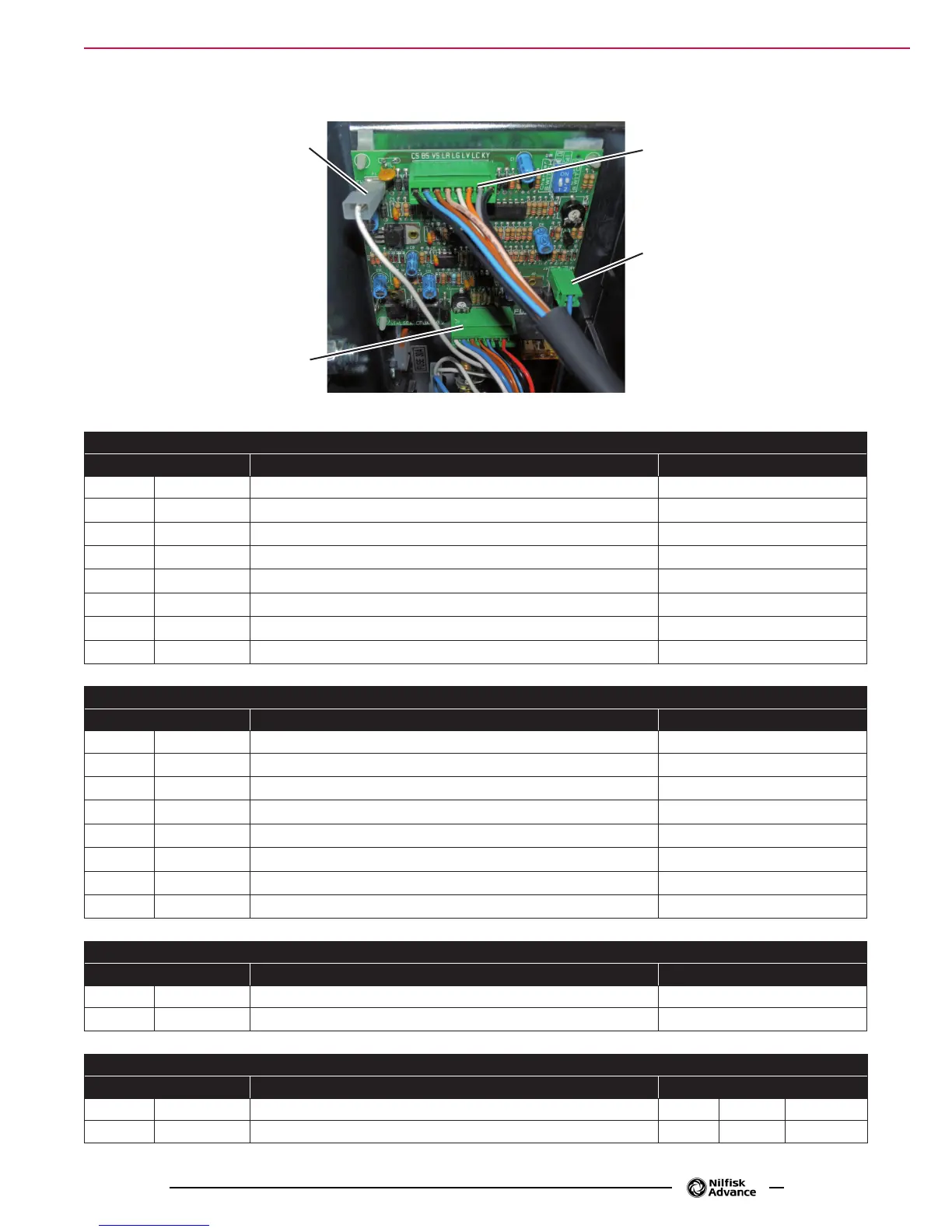
J1
J3
F1
J2
P200010
J1 - 8 WAY-CONNECTOR
PIN Description Voltage Ref. to B -
1 CS Switch power supply 24V
2 BS Brush switch activation 24V
3 VS Vacuum system switch 24V
4 LR Red LED (<=> EB2 PIN 2) 0V
5 LG Yellow LED (<=> EB2 PIN 3) 0V
6 LV Green LED (<=> EB2 PIN 4) 0V
7 LC Common LED (<=> EB2 PIN 1) 5V
8 KY Brush system switch 24V
J2 - 8 WAY-CONNECTOR
PIN Description Voltage Ref. to B -
1 CT Relay power supply 24V
2 BT Brush relay power supply 0V
3 VT Vacuum system relay power supply 0V
4 S- Brush motor current detection - 0V
5 S+ Brush motor current detection + 0V
6 V- Power supply - 0V
7 V+ Power supply + 24V
8 BL Not used -
J3 - 3 WAY-CONNECTOR
PIN Description Voltage Ref. to B -
1 W+ Solenoid valve + 24V
2 W- Solenoid valve - 0V
F1 - FASTON
PIN Description Voltage Ref. to B -
1 6.3 mm Power supply from battery charger 24V 24V 24V (*)
2 4.8 mm Not used -
 Loading...