Alarm Pin Assignments
86
7210 SAS-M CHASSIS INSTALLATION GUIDE
3HE 10089 AAAA TQZZA Edition 01 Issue: 07
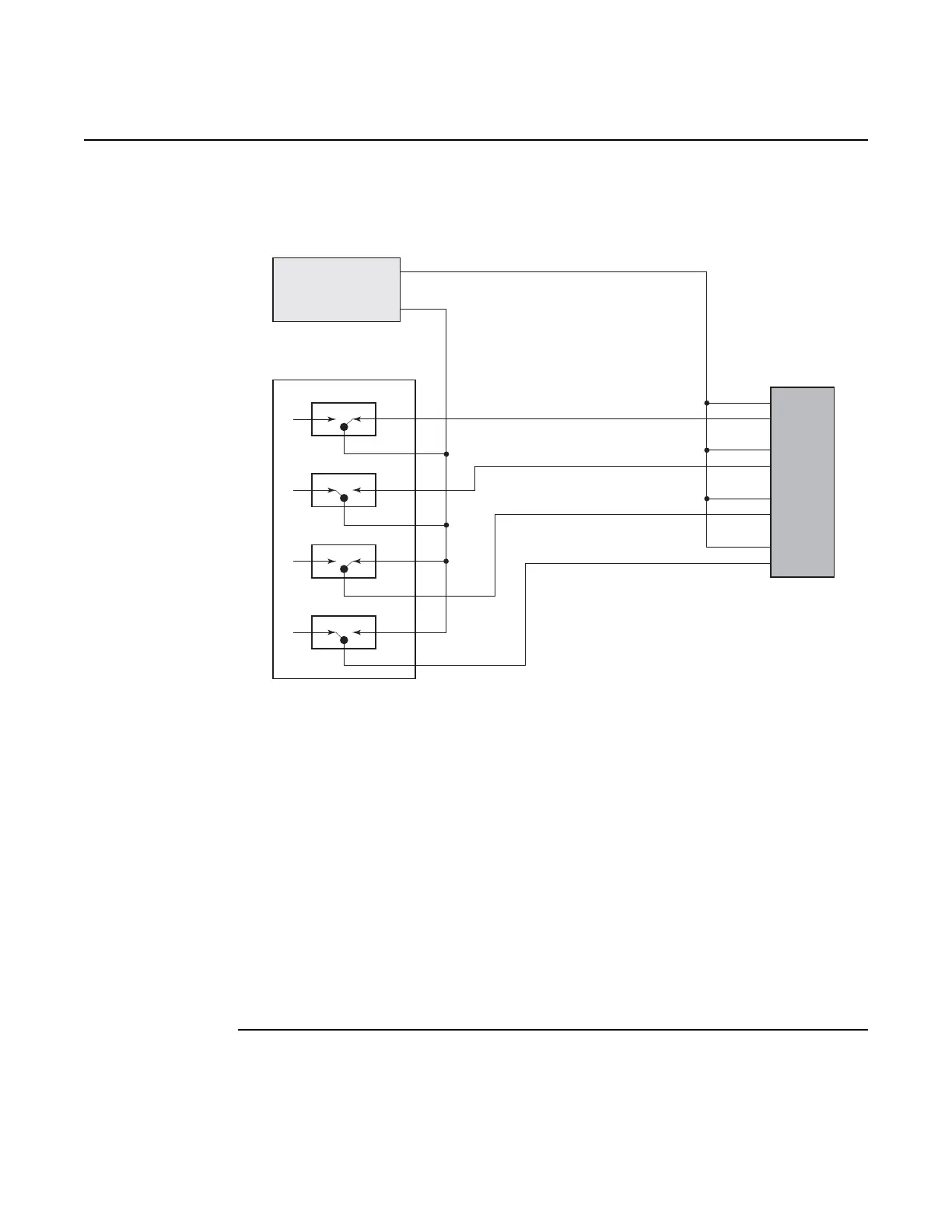
Figure 17 Alarm Input Connection Diagram
RTN refers to the negative side of the floating external power supply. This power
supply must not be connected to chassis ground and should be 18 to 50 VDC at 100
ma.
Major and critical alarm dry relay contact outputs are provided on pins 3,10,11 and
1,2,9. These reflect the major and critical alarms output by the box and can be
manually cleared by pressing the ACO button.
The 4 alarm inputs are customer configurable to monitor alarms provided by
additional equipment. These inputs require a separate DC power supply between 18
to 50 VDC at 100ma. The power supply outputs must be isolated from chassis
ground; for example, do not connect the alarm power supply return to chassis or rack
ground.
7210_SAS_DC
active
active
active
active
–
+
off
off
off
off
Alarm 1
Alarm in 1
Pin 8 +
Pin 15 -
Pin 7 +
Pin 14 -
Pin 6 +
Pin 13 -
Pin 5 +
Pin 12 -
Alarm
DB15
Alarm in 2
Alarm in 3
Alarm in 4
External Alarm Relays
On Other Equipment
DC Power Supply
18-50 VDC @ 100 mA
Power Supply Must be
Floating or Isolated from
Chassis Ground
Alarm 2
Alarm 3
Alarm 4
 Loading...