Product Description Remote Annunciator
10 RP-1001 15150:F 05/24/2001
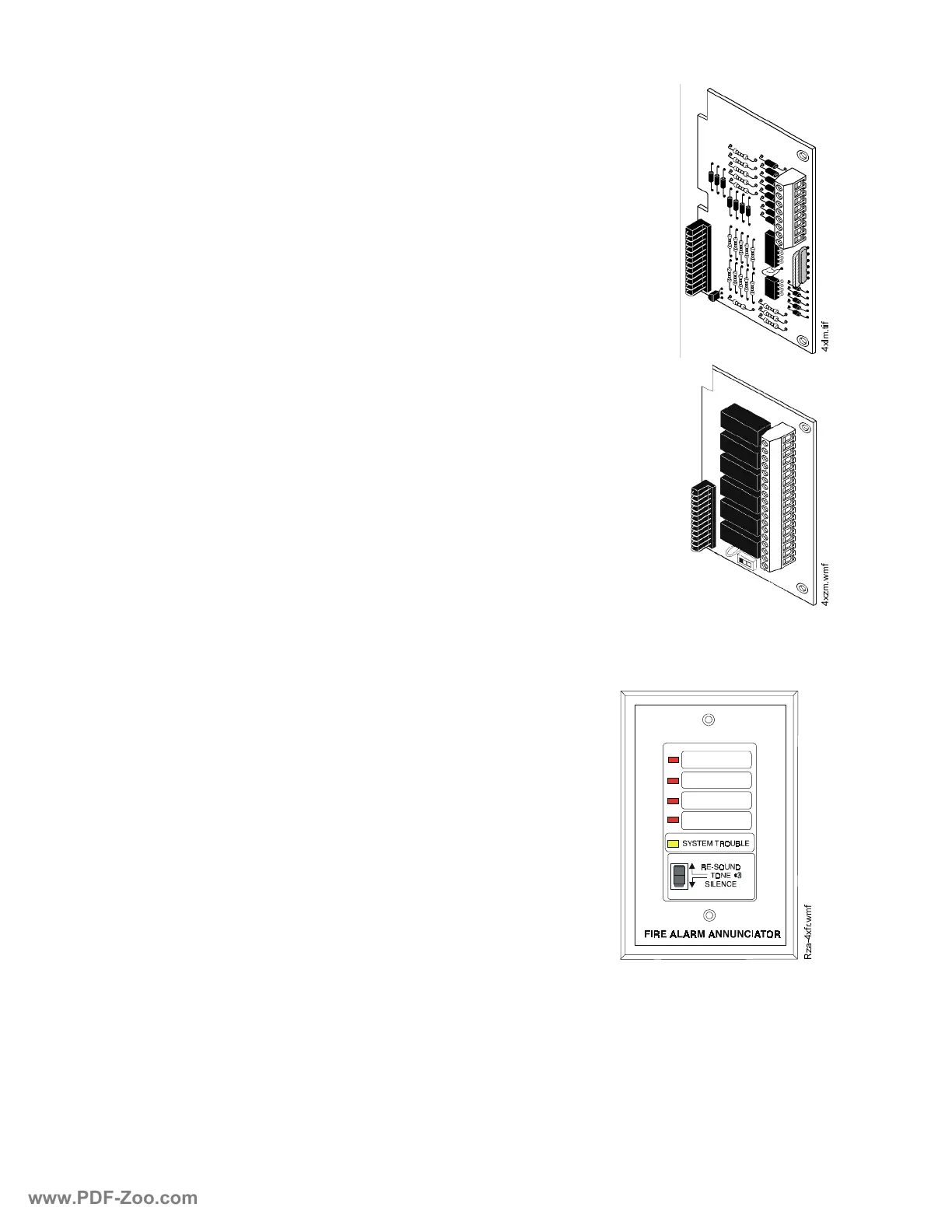
/(',QWHUIDFH0RGXOH;/0
The LED Interface Module supports the RZA-4X Remote Annunciator
module. Annunciator wiring is supervised for open conditions by this
module. The Annunciator Driver Module mounts to the main board on
the J8 option connector.
Specifications
Maximum voltage/current, each output: 27.6 V / 8 mA.
Note: Outputs are power-limited.
=RQH5HOD\0RGXOH;=0
The Zone Relay module provides Form-C contacts for the following:
• Alarm/Waterflow Bell*
• Waterflow/Supervisory Bell*
• Releasing Circuit 1*
• Supervisory Bell/Release Circuit 2*
• System Alarm
• System Trouble
* As a jumper option, these relays can be made Silenceable.
Specifications
Dry Form-C contacts rated: 2.0 amps @ 30 VDC (resistive), 0.5 amps
@ 30 VAC (resistive).
5HPRWH$QQXQFLDWRU
5HPRWH$QQXQFLDWRU5=$;
The Remote Annunciator mounts on a standard single-gang
box, and provides LED indication of the following:
• Alarm/Waterflow Bell (red)
• Waterflow/Supervisory Bell (red)
• Releasing Circuit 1 (red)
• Supervisory Bell/Release Circuit 2 (red)
• System Trouble LED (yellow)
A Local Trouble Sounder and Silence Switch are also pro-
vided. All LED wiring is supervised for open conditions.
Any open condition will cause the System Trouble LED to
illuminate.
Note: The Remote Annunciator requires the use of an LED
Interface module (4XLM).
[OPWLI[]PZPI
5]D[IUZPI
www.PDF-Zoo.com

 Loading...


