Power-Up Procedure Installation Procedure
RP-1001 15150:F 05/24/2001 25
'LVFKDUJH7LPHU
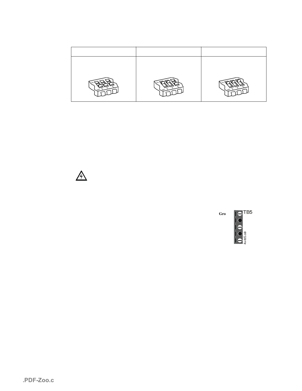
Select the desired Discharge Timer setting by setting SW1 DIP switches 3, 4 and 5.
For NFPA 13 and 15 applications Timer must be set to DISABLED.
For NFPA 16 applications, Timer may be set to 10 MINUTES or 15 MINUTES.
Discharge Timer Notes:
1. Timer will always start at Zone 2 normal to alarm transition. Upon time-out, corresponding
release circuits will shut off.
2. Zone 1 will override timer shutoff (except for Mode #4–Split Release).
3RZHU8S3URFHGXUH
WARNING: Prior to energizing this panel, notify all personnel and authorities,
including any personnel who may be working on, around, or near this unit.
CAUTION: Observe polarity of batteries. Improper connection will cause damage
and VOID WARRANTY. Do not connect battery leads until instructed to do so per
the power-up procedure. System will be operational and could damage the PC
board or injure personnel.
1.
Wire Primary Power Connections.
Primary power
required for the RP-1001 and RP-1001C panels is 120 VAC,
50/60 Hz, 1.2 amps. Primary power required for the
RP-1001E is 220/240 VAC, 50/60 Hz, 0.6 amps.
Overcurrent protection for this circuit must comply with
Article 760 of the National Electrical Code (NEC) and/or
local codes. Use #14 AWG or larger wire with 600 volt
rating.
The power supply will operate normally and the panel will be fully operational from 102-132
VAC. However, to keep the batteries fully charged, input power must be maintained at nom-
inal 120 VAC. A separately fused and protected power connection to the panel should be
supplied to prevent voltage fluctuation and interruption of power.
2.
Apply Primary Power.
Notify personnel who may be working with the AC power circuits
before removing the “Out of Service” tag and restoring power to the circuit. The green AC
power LED will illuminate. The Trouble LED will illuminate until battery power is applied.
Disabled 10 Minutes 15 Minutes
Switch #3 OFF,
Switch #4 OFF,
Switch #5 OFF
Switch #3 ON,
Switch #4 ON,
Switch #5 OFF
Switch #3 ON,
Switch #4 ON,
Switch #5 ON
7%
Ground
(Not Used)
Neutral
(Not Used)
Hot
[WEFGU
www.PDF-Zoo.com

 Loading...


