Optional Meters Product Description
RP-1001 15150:F 05/24/2001 11
2SWLRQDO0HWHUV
9ROWDJHDQG&XUUHQW0HWHUV;00
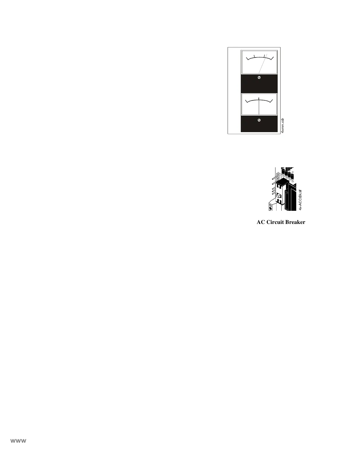
The Meter Module provides a voltmeter to measure the volt-
age across the batteries and an ammeter to measure the
charging current to the batteries. The meters are provided as
an assembly that mounts to the lower left-hand corner of the
cabinet.
6SHFLILFDWLRQV
$&3RZHU
For RP-1001 and RP-1001C: 120 VAC, 50/60 Hz, 1.2 amps
For RP-1001E: 220/240 VAC, 50/60 Hz, 0.6 amps
Wire size: minimum #14 AWG with 600V insulation
%DWWHU\OHDGDFLGRQO\
Maximum Charging Circuit: 27.6V, 1.5 amps
Maximum Battery Capacity: 18 AH. (Batteries larger than 12 AH
require Notifier BB-17 or other UL-listed external battery cabinet.)
Minimum Battery Capacity: 7 AH
,QLWLDWLQJ'HYLFH&LUFXLWV
Power-limited circuitry
Operation: Style B (Class B)/ Style D (Class A)
Normal Operating Voltage: 24 VDC (ripple = 1.0V p-p)
Alarm current: 15 mA minimum
Short circuit current: 40 mA maximum
Maximum detector current in standby: 2 mA (max) per zone
Maximum loop resistance: 100 ohms
End-of-Line Resistor: 4.7K, 1/2-Watt (part # 71252 UL listed)
Detector loop current is sufficient to ensure operation of one alarmed detector per zone.
Supervisory current: 5 mA (including End-of-Line Resistor)
1RWLILFDWLRQ$SSOLDQFHDQG5HOHDVLQJ&LUFXLWV
Power-limited circuitry
Maximum allowable voltage drop due to wiring: 2 VDC
Normal Operating Voltage: 24 VDC
Total current available to all external devices: 2.25 amps.
Maximum signaling current per circuit: 1.5 amps
End-of-Line Resistor: 4.7K, 1/2-Watt (part # 71252 UL listed)
$ODUPDQG7URXEOH5HOD\V
Dry Form-C contacts rated: 2.0 amps @ 30 VDC (resistive), 0.5 amps @ 30 VAC (resistive). Any
power connected to these relay contacts must come from a power-limited supply. Fail-safe opera-
tion ensures trouble relay functioning under loss of both primary power (AC) and secondary
(battery power).
0
10
20
30
DC VOLTS
0
5
5
DC AMPERES
[PPFGU
[$&&W%NWLI
AC Circuit Breaker
www.PDF-Zoo.com

 Loading...


