Installation Procedure UL Power-limited Wiring Requirements
14 RP-1001 15150:F 05/24/2001
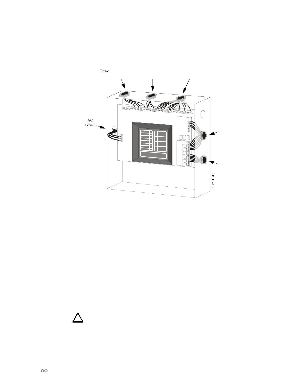
8/3RZHUOLPLWHG:LULQJ5HTXLUHPHQWV
Power-limited and non-power-limited circuit wiring must remain separated in the cabinet. All
power-limited circuit wiring must remain at least 0.25 in (6.35 mm) away from any non-power-lim-
ited circuit wiring. Furthermore, all power-limited circuit wiring and non-power-limited circuit
wiring must pass through separate knockouts and/or conduits.
3RZHU)HHG:LULQJ
Disconnect the circuit breaker in the AC main breaker panel. Tag it “Out of Service” and refer to
“Power-Up Procedure” in Section 2.11 before closing AC breaker.
Determine the number of conductors required for the devices to be employed. Pull required
conductors into the box through the knockout provided.
Batteries are shipped separately and should be mounted only after the enclosure has been installed,
the conduit connected, and all wiring pulled, tested, and made ready to be terminated.
All wiring should be in accordance with the National and/or Local codes for fire alarm systems,
including “UL Power-limited Wiring Requirements” in Section 2.2.
Mount the transformer onto the studs of the left-hand side of the backbox. Reinstall the printed
circuit boards on the stand-offs provided within the enclosure. Connect the free end of the trans-
former cable to J1 on the printed circuit board.
WARNING: Do not apply Primary or Secondary power to the board
at this time.
If servicing the panel, check to insure that release devices (i.e. solenoids) are mechanically and
electrically disabled to avoid inadvertent agent discharges.
Wire electrical circuits as described in the following sections.
Figure 2.1 UL Power-limited Wiring Requirements
USSOFGU
AC
Power
Power-limited
Circuits
Power-limited
Circuits
Non-Power-
limited Circuits
Power-
limited
Circuit
Non-
Power-
limited
Circuit
www.PDF-Zoo.com

 Loading...


