Optional Boards Product Description
RP-1001 15150:F 05/24/2001 9
2YHUYLHZRI',36ZLWFK6:)XQFWLRQV
2SWLRQDO%RDUGV
The control panel has mounting slots for two optional boards. Any two
of the three optional modules may be installed.
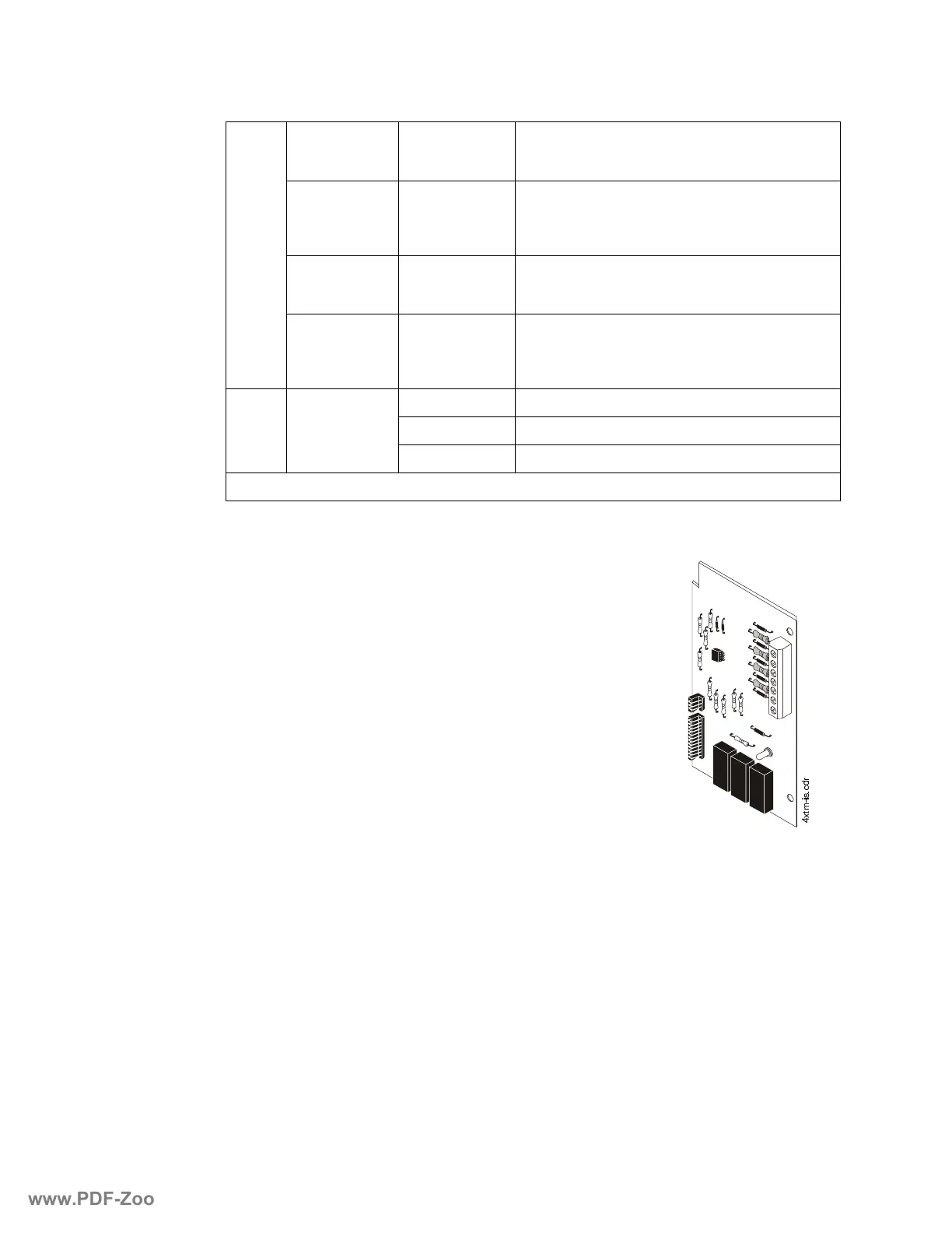
7UDQVPLWWHU0RGXOH;70
The Transmitter Module provides a supervised output for local energy
municipal box transmitter (for NFPA 72 Auxiliary Fire Alarm System)
and alarm and trouble reverse polarity circuits (for NFPA 72 Remote
Station Fire Alarm System). Also included is a DISABLE switch and
disable trouble LED.
As a jumper option, the alarm reverse polarity circuit will open on trou-
ble if no alarm exists.
Specifications for Local Energy Municipal Box service (NFPA 72
Auxiliary Fire Alarm System)
Supervisory current: 5.0 mA.
Trip current: 0.35 amps (subtracted from Notification Appliance power).
Coil Voltage: 3.65 VDC.
Coil resistance: 14.6 ohms.
Maximum allowable wire resistance between panel and trip coil: 3 ohms.
Municipal Box wiring can leave the building.
Specifications for Remote Station service (NFPA 72 Remote Station Fire Alarm System)
Maximum load for each circuit: 10 mA.
Reverse polarity output voltage: 24 VDC.
Remote Alarm and Remote Trouble wiring can leave the building.
DIP 1,
DIP 2
Single Hazard,
Two Zone
OFF, OFF
• NAC 1 and 3 activated by Zone 1 OR 2
• NAC 2 activated by Waterflow on Zone 3
• NAC 4 activated by Supervisory on Zone 4
Single Hazard,
Cross Zone
ON, OFF
• NAC 1 activated by Zone 1 OR 2
• NAC 2 activated by Waterflow on Zone 3
• NAC 3 activated by Zone 1 AND Zone 2
• NAC 4 activated by Supervisory on Zone 4
Dual Hazard,
Combined Release
OFF, ON
• NAC 1 activated by Zone 1 OR 2 OR Zone 3
• NAC 2 activated by Supervisory on Zone 4
• NAC 3 and 4 activated by Zone 1 OR Zone 2
Dual Hazard,
Split Release
ON, ON
• NAC 1 activated by Zone 1 OR 2 OR Zone 3
• NAC 2 activated by Supervisory on Zone 4
• NAC 3 activated by Zone 1
• NAC 4 activated by Zone 2
DIP 3,
DIP 4,
DIP 5
Discharge Timer
OFF, OFF, OFF Disabled
ON, ON, OFF 10 Minutes
OFF, OFF, OFF 15 Minutes
Note: See “Setting Mode of Operation” in Section 2.10 for a more detailed explanation of DIP switch functions.
[WPLVFGU
www.PDF-Zoo.com