Product Description Circuits
8 RP-1001 15150:F 05/24/2001
-
-
-
-
Initiating Device
Circuits
Supervised/Power-Limited
Style D (Class A)
Style B (Class B)
Notification
Appliance Circuits
(Supervised/Power-Limited)
Style Z (Class A)
Style Y (Class B)
24 VVU
RMS-Regulated
24 VR
Regulated
Resettable
24 VNR
Regulated
Nonresettable
1234
Releasing
Circuits
Relays
Trouble
Contacts
Alarm
Contacts
12
34
4XTM
or
4XZM
Note: If a module is
installed in this position,
cut jumper “OPT1”
on the main board.
4XTM
or
4XLM
or
4XZM
Note: If a module is
installed in this position,
cut jumper “OPT2”
on the main board.
Micro Fail LED
Not Used
Discharge Timer
Discharge Timer
Cross Zone
Dual Hazard
Discharge Timer
Ground
Fault LED
Battery Fail LED
Batteries
Optional Ammeter
Connection
Optional Voltmeter
Connection
;53DFGU
Ground
Neutral
Hot
AC Circuit Breaker
Transformer
AC Power
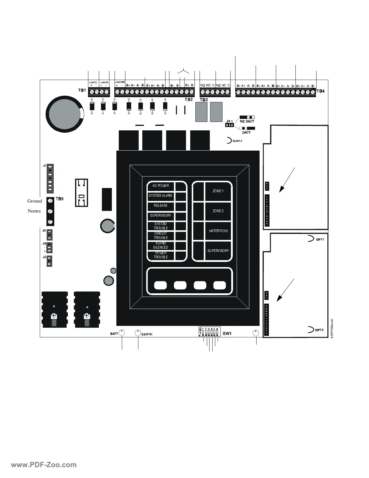
Figure 1.1 RP-1001 Installation Diagram
Water-
flow
Super-
visory
=21(
=21(
:$7(5)/2:
683(59,625<
Zone 1
Zone 2
$& 32:(5
6<67(0 $/$50
5(/($6(
683(59,625<
6<67(0
7528%/(
&,5&8,7
7528%/(
$/$50
6,/(1&('
32:(5
7528%/(
www.PDF-Zoo.com