NVIDIA Jetson TX2/TX2i OEM Product Design Guide
JETSON TX2/TX2i OEM PRODUCT | DESIGN GUIDE | 20180618 102
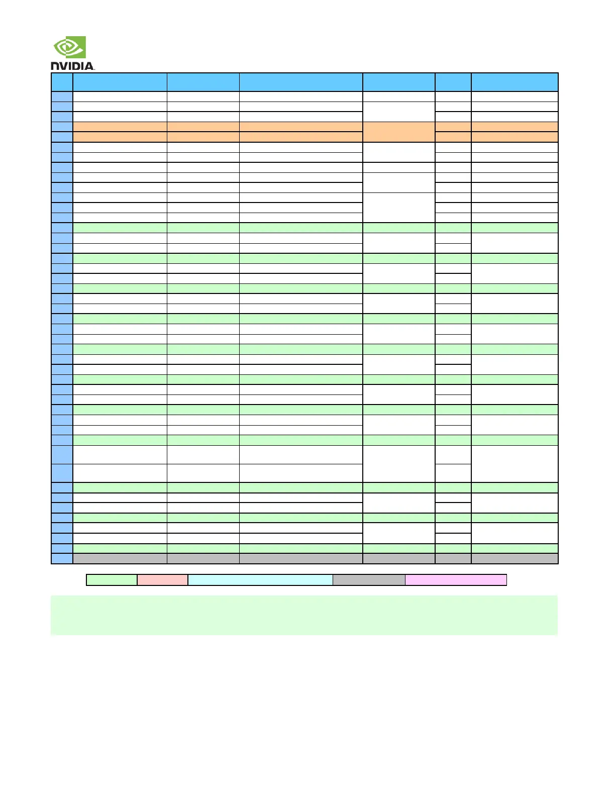
Usage on the Carrier
Board
I2S Audio Port 2 Data Out
Optional source of
UART on Exp. Header
Proximity sensor Interrupt or GPIO
SPI 2 Master In / Slave Out
SD Card power switch Enable
DisplayPort 0 Lane 3 or HDMI Clk Lane
AC-Coupled on carrier
board
DisplayPort 0 Lane 3+ or HDMI Clk Lane+
DisplayPort 0 Lane 0 or HDMI Lane 2
AC-Coupled on carrier
board
DisplayPort 0 Lane 0+ or HDMI Lane 2+
PCIe 1 Receive+ (PCIe #2 Lane 0 muxed
w/USB 3.0 Port #0)
USB 3.0 Type A
(Default) or M.2 Key E
PCIe PHY, AC-Coupled on
carrier board
PCIe 1 Receive (PCIe #2 Lane 0 muxed
w/USB 3.0 Port #0)
PCIe 0 Receive+ (PCIe IF #0 Lane 0)
PCIe PHY, AC-Coupled on
carrier board
PCIe 0 Receive (PCIe IF #0 Lane 0)
RSVD on Jetson TX2 (available on TX2i)
Redefined for Jetson TX2i
1. The Usage/Description column uses the module port/lane/interface references.
2. In the Type/Dir column, Output is from the module. Input is to the module. Bidir is for Bidirectional signals.
3. These pins are handled as Open-Drain on the carrier board