NVIDIA Jetson TX2/TX2i OEM Product Design Guide
JETSON TX2/TX2i OEM PRODUCT | DESIGN GUIDE | 20180618 29
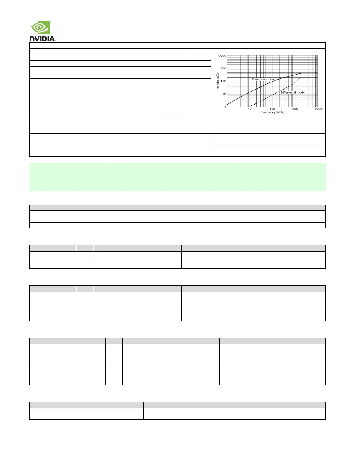
Common-mode Choke (Only if needed. Place near connector.)
Common-mode impedance @100MHz Min/Max
Differential TDR impedance @T
R
-200ps (10%-90%)
FPC (Additional length of Flexible Printed Circuit Board)
The FPC routing should be included for PCB trace calculations (max length, etc.)
Strongly recommend being
the same as PCB or better
If worse than PCB, the PCB & FPC length must be re-
estimated
Connector used must be USB-IF certified
1. Longer trace lengths may be possible if the total trace loss is equal to or better than the target. If the loss is greater, the
max trace lengths will need to be reduced.
2. Recommend trace length matching to <1ps before Vias or any discontinuity to minimize common mode conversion.
3. Place GND Vias as symmetrically as possible to data pair Vias.
Common USB Routing Guidelines
If routing to USB device or USB connector includes a flex or 2
nd
PCB, the total routing including all PCBs/flexes must be used for the max trace & skew
calculations.
Keep critical USB related traces away from other signal traces or unrelated power traces/areas or power supply components
Table 19. Module USB 2.0 Signal Connections
-mode chokes close to
connector. ESD Protection between choke
& connector on each line to GND
USB Differential Data Pair: Connect to USB connector, Mini-Card
Socket, Hub or other device on the PCB.
Table 20. Miscellaneous USB 2.0 Signal Connections
See reference
design for VBUS power filtering.
USB0 VBus Detect: Connect to VBUS pin of USB connector receiving
USB0_+/– interface. Also connects to VBUS power supply if host mode
supported.
USB Identification: Connect to ID pin of USB OTG connector receiving
USB0_P/M interface.
Table 21. USB 3.0 Signal Connections
USB_SS0_TX+/– (USB 3.0 Port #0)
PEX_RFU_TX+/– (USB 3.0 Port #1)
USB_SS1_TX+/– (USB 3.0 Port #2)
Series 0.1uF caps. Common-mode chokes &
ESD protection if these are used.
USB 3.0 Differential Transmit Data Pairs: Connect
to USB 3.0 connectors, hubs or other devices on the
PCB.
USB_SS0_RX+/– (USB 3.0 Port #0)
PEX_RFU_RX+/– (USB 3.0 Port #1)
USB_SS1_RX+/– (USB 3.0 Port #2)
If routed directly to a peripheral on the board,
AC caps are needed for the peripheral TX lines.
Common-mode chokes & ESD protection, if
these are used.
USB 3.0 Differential Receive Data Pairs: Connect
to USB 3.0 connectors, hubs or other devices on the
PCB.
Table 22. Recommended USB observation (test) points for initial boards
One for each of the USB 2.0 data lines (D+/-)
Near the module connector & USB device. USB connector pins can serve as test points.
One for each of the USB 3.0 output lines used (TXn_+/-)
Near USB device. USB connector pins can serve as test points