EasyManuals Logo
Home>Nvidia>Microcontrollers>JETSON TX2

Nvidia JETSON TX2 User Manual

Nvidia JETSON TX2
103 pages
To Next Page IconTo Next Page
To Previous Page IconTo Previous Page
Page #35 background imageLoading...
Page #35 background image
NVIDIA Jetson TX2/TX2i OEM Product Design Guide
JETSON TX2/TX2i OEM PRODUCT | DESIGN GUIDE | 20180618 35
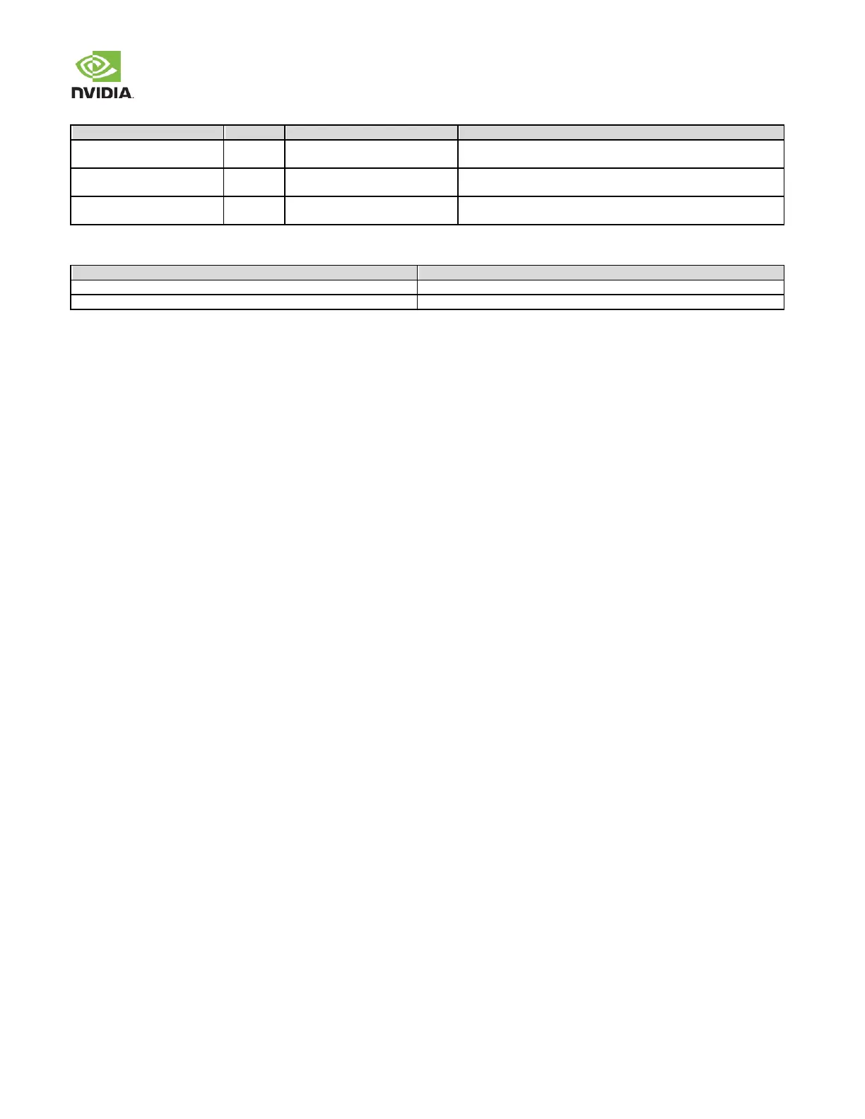
Table 27. SATA Signal Connections
Module Pin Name
Type
Termination
Description
SATA_TX+/
DIFF OUT
Series 0.01uF Capacitor
Differential Transmit Data Pair: Connect to SATA+/ pins of SATA
device/connector through termination (capacitor)
SATA_RX+/
DIFF IN
Series 0.01uF Capacitor
Differential Receive Data Pair: Connect to SATA+/ pins of SATA
device/connector through termination (capacitor)
SATA_DEV_SLP
O
1.8V to 3.3V level shifter
SATA Device Sleep: Connect through level shifter to matching pin
on device or connector (pin 10 of Connector show in example).
Table 28. Recommended SATA observation (test) points for initial boards
Test Points Recommended
Location
One for each of the SATA_TX_+/ output lines.
Near SATA device. Connector pins may serve as test points if accessible.
One for each of the SATA_RX_+/ input lines.
Near the module connector.

Other manuals for Nvidia JETSON TX2

Questions and Answers:

Question and Answer IconNeed help?

Do you have a question about the Nvidia JETSON TX2 and is the answer not in the manual?

Nvidia JETSON TX2 Specifications

General IconGeneral
BrandNvidia
ModelJETSON TX2
CategoryMicrocontrollers
LanguageEnglish

Related product manuals