Instruction Manual Easygraph
Page 43
If the “rm” button is active, as in the default setting,
the reference body is calculated from the mean
central curvature radius and an eccentricity 0.1
greater than that of the cornea. These parameters
are ideal for displaying normal or astigmatic corneas,
and they are frequently used in manual topometry
programs. Activating the “rf” button causes the
reference body to be calculated using the flat central
curvature radius and an eccentricity 0.1 greater than
that of the cornea. This setting is especially suitable
for cases of keratoconus, as the position of the apex
is displayed immediately.
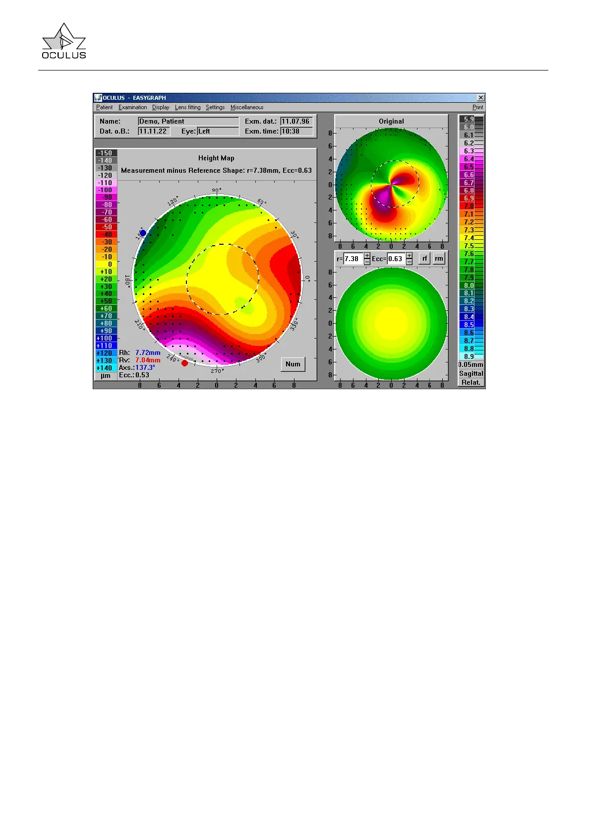
The large map on the left is a graphic representation
of height data shown in terms of differences in
height between the measuring point (cornea) and the
reference body. The figures at the bottom left give
the simulated ophthalmometric values including axis
position and mean eccentricity at 30°. Clicking the
“Num” button displays a polar coordinate system
showing local height data. This permits an
assessment of the fit of spheroaspherical or
quadrant lenses of known apex depth.
The "Height Map" window is bordered by two color
bars. The right color bar corresponds to that of the
overview display and represents curvature values
(mm or D). The left color bar contains height data,
classifying deviations from the reference body into
10 µm intervals. Clicking with the left mouse button
permits the user to change the resolution for better
readability.
Clicking with the left mouse button in any of the color
maps causes the curvature or height value at that
location to be displayed in all of the maps.