BM/2/AS
Installation and connections
GB - 12
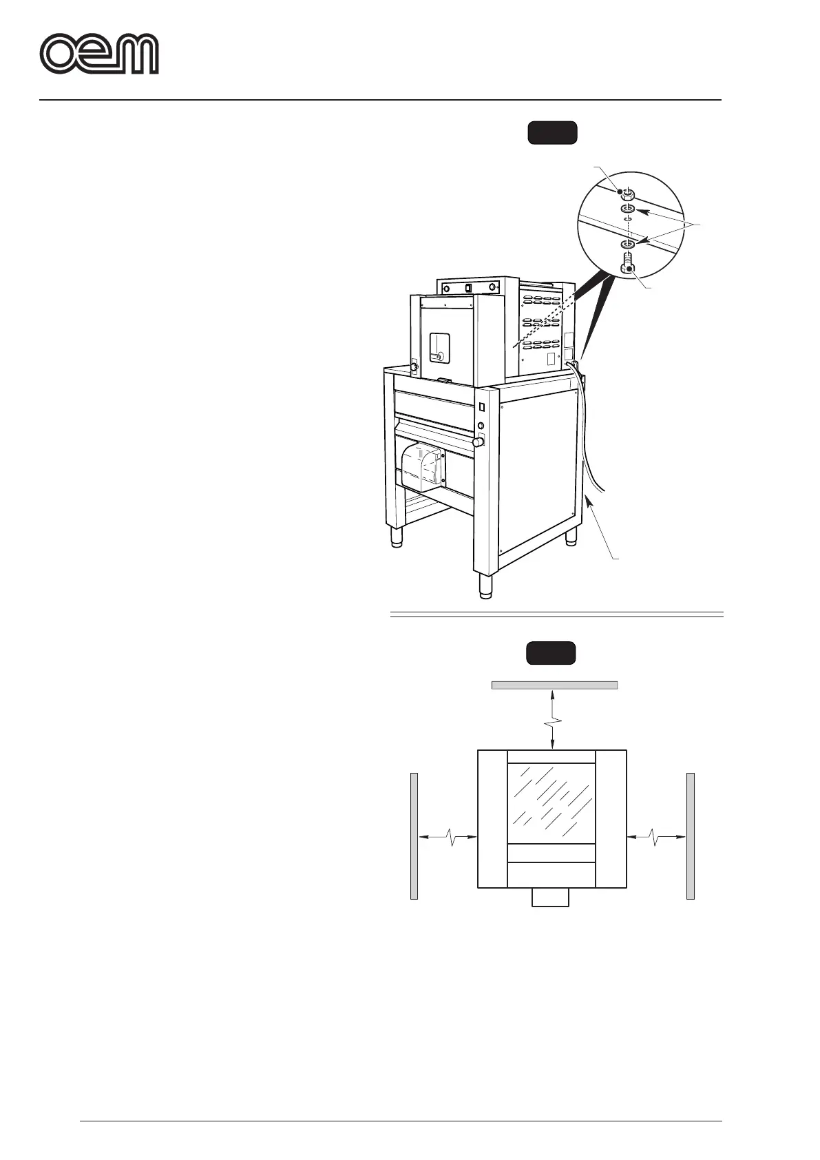
FIG. 4
300 mm
300 mm
300 mm
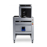
FIG. 3
8
9
7
• Remove the rear panel (7) and fasten the two ma-
chines with two screws (8), washers (9) and nut (10).
3.1.a - MACHINE POSITIONING
The machine shall be positioned according to the
instructions reported in Fig 2, since they indicate the
minimum safety range to be considered in order to allow
the user or the technician to properly carry out any work
and/or maintenance operations.