BM/2/AS
Installation and connections
GB - 13
FIG. 5
1
5
2
4
3
3
A
4
3
3
5
3
6
7
B
9
10
8
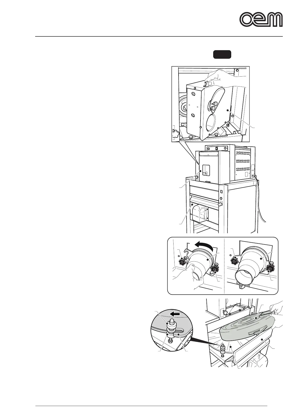
3.2 - COMPONENT ASSEMBLY (Fig. 5)
With the machine off:
• Raise the door (1).
• Open the interior door (2).
• Loosen the knobs (3) and t the cone (4) turning it in
the direction indicated by the arrow “A”, then lock the
cone (4) into place by tightening the knobs (3).
• Open the drawer (5) and t the bell (6) on the rotary
plate (7).
• Check that the ring nuts (8) are completely unscrewed,
then t the hook (9) onto the pins (10) turning the bell
(6) in the direction indicated by the arrow “B” until it
locks into place.