43502101TH Rev.1 152 /
Oki Data CONFIDENTIAL
3.3.2 TQSB-2 PCB
(1) Remove the pulse motor (see 3.3.1).
(2) Remove the connectors Q, R from the GRT PCB P.
(3) Remove the screw S and remove the GRT PCB P.
Note :
Refer to Detall A in the previous page.
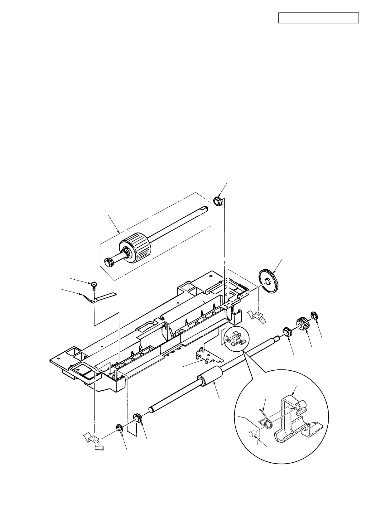
3.3.3 Hopping Roller Shaft Assy and One-way Clutch Gear
(1) Follow up to step (3) of 3.3.1 and remove the hopping frame assy.
(2) Remove the screw 1 and remove the earth plate 2. Remove the sensor lever (T) 7 and remove
the transion spring D and remove the ground plate 6. Remove the gear 3 and remove the metal
bush 5 and hopping roller shaft assy 4.
(3) Remove the E-ring A and remove the one-way clutch gear B on the right side of the feed roller
0.
Note :
The metal bush C also comes off. Be careful not to lose it.
4
1
2
3
5
A
B
C
0
9
8
6
D
7
Shaft
The tension lever and the sensor lever need concurrent replacing.