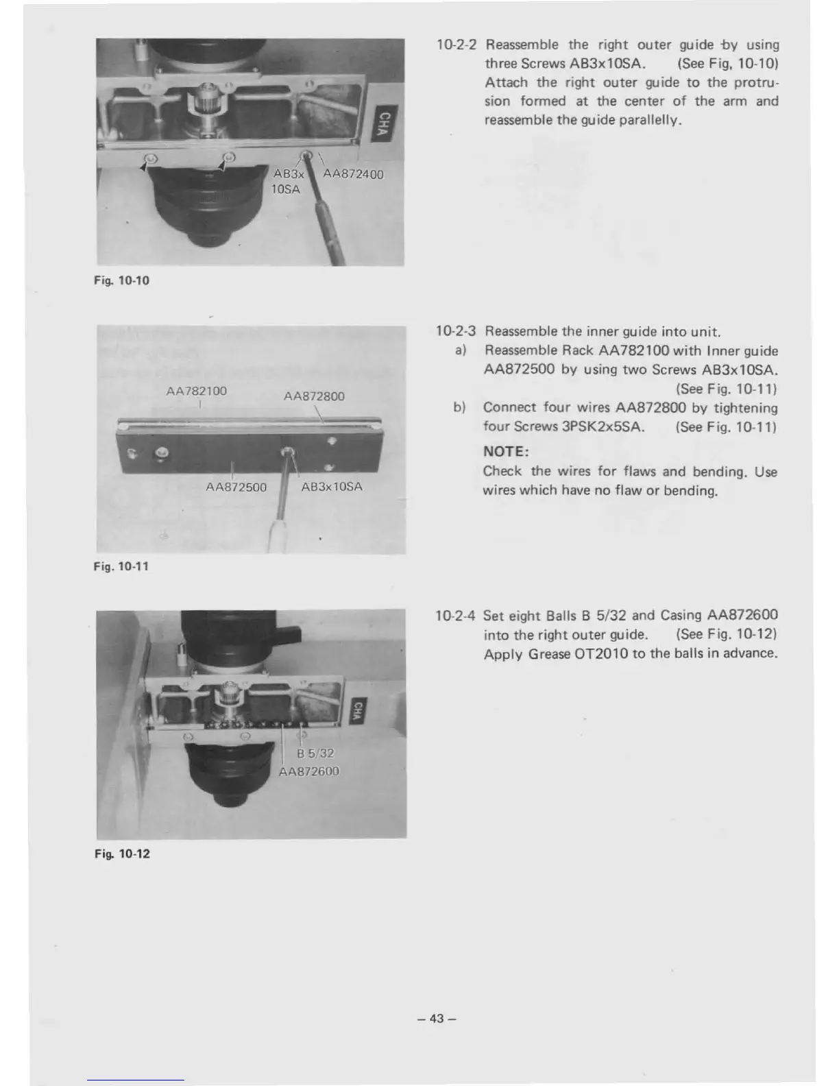
Fig. 10-10
10·2·2 Reassemble
the
right
ouler
guide
-by
using
three Screws AB3xl0SA. (See Fig, 10-10)
Attach
the
right
outer
guide
to
the
protru·
sion formed
at
the center
of
the
arm and
reassemble the
gu
ide parallelly.
•
~
.
~
• I
1\.
Fig. 10-11
AA782100
I
AA872500
AA872800
AB3xl0SA
10-2-3
a)
b)
Reassemble
the
inner guide into unit.
Reassemble Rack AA782100 with Inner guide
AA872500 by using two Screws AB3xl0SA.
(See Fig. 10·
11
)
Connect four wires AA872800 by tightening
four Screws 3PSK2x5SA. (See Fig. 10-11)
NOTE:
Check the wires for flaws and bending.
Use
wires which have no flaw
or
bending.
Fig. 10-12
IJ
10-2-4
Set
eight Balls B
5/32
and Casing AA872600
into
the
right
outer
guide. (See Fig. 10-12)
Apply Grease
OT2010
to
the
balls
in
advance.
-43-