88
6.3 Insertion of the lamp
CLV-190 INSTRUCTION MANUAL
Ch.6
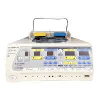
6 Place heat sink (A) and heat sink (B) so that
their undersides are flat and close the heat sink
clamp firmly.
Figure 6.11
Be sure to tighten the heat sink clamp firmly. Poor heat radiation may result in
equipment damage, examination lamp ignition failure, and a considerable
decrease in the life of the examination lamp.
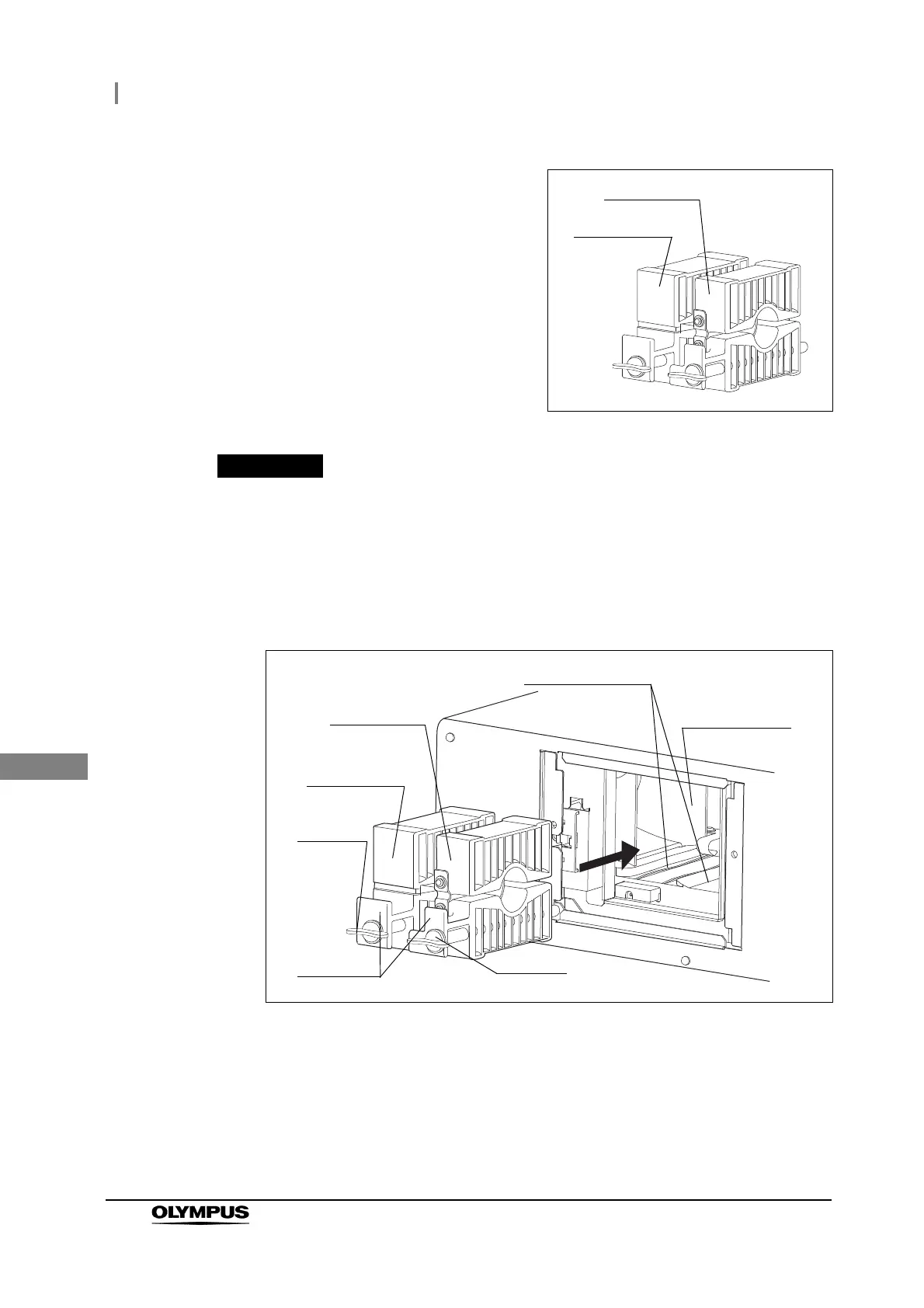
7 Insert both heat sinks (A) and (B) simultaneously into the lamp chamber along the
insertion grooves.
Figure 6.12
Heat sink (A)
Heat sink (B)
Insertion groove
Heat sink (A)
Heat sink (B)
Knob (B)
Projection
Knob (A)
Lamp chamber
 Loading...