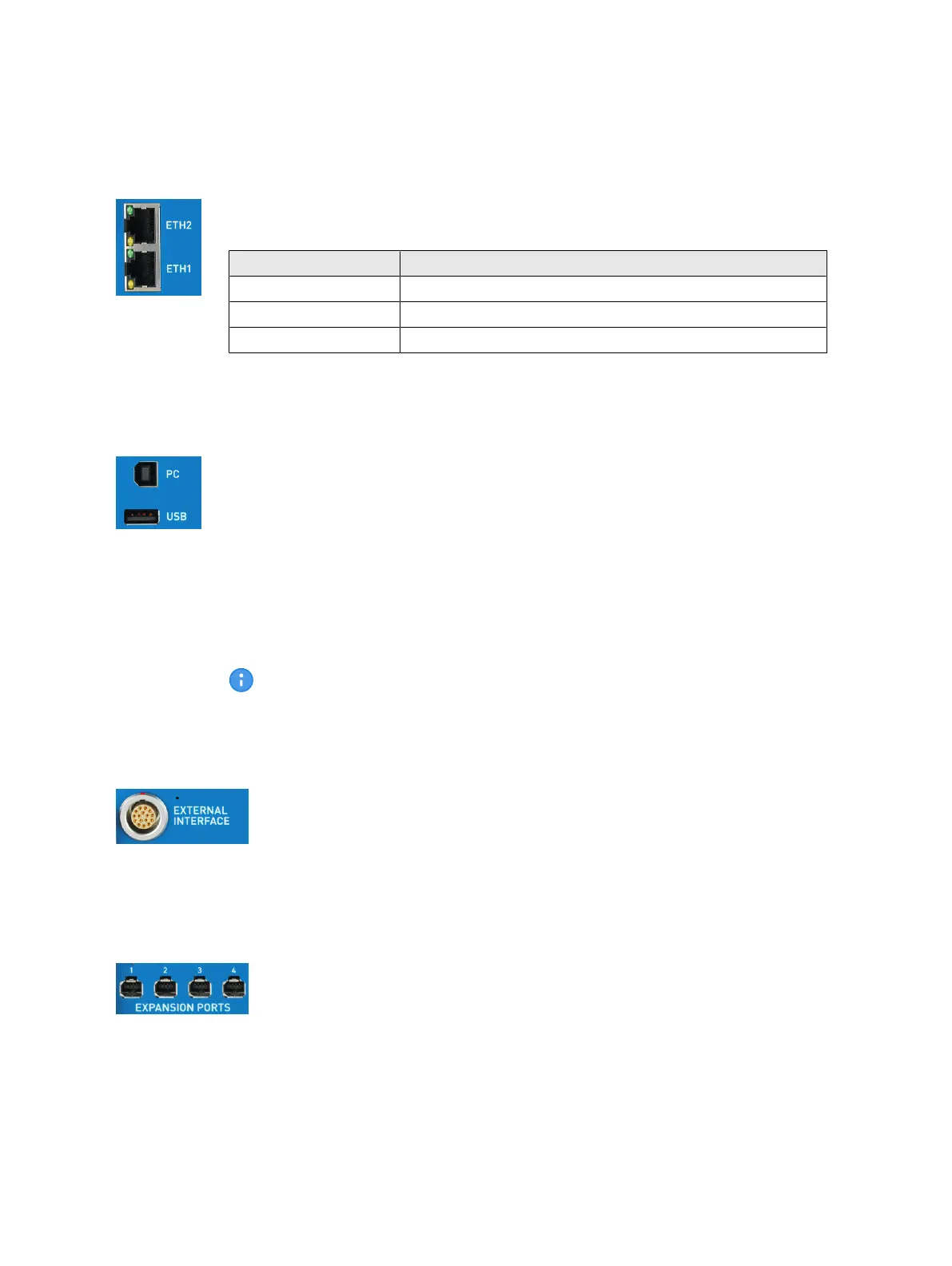
2.2.3 Ethernet interfaces
10/100/1000Base-TX Ethernet ports with Power over Ethernet (PoE) capability. The
port LEDs indicate the link speed and will blink in case of traffic:
Link speed LED behavior
10 Mbps Yellow LED active
100 Mbps Green LED active
1000 Mbps Yellow and green LED active
Technical data → Communication interfaces on page 38.
2.2.4 USB ports
The PC port (USB type B) connects the CMC 430 to the USB port of the controlling
computer.
The USB port (USB type A) is currently used for the USB Wi-Fi adapter only. The
USB Wi-Fi adapter is required for connecting the CMC 430 to a Wi-Fi network. Only
use the Wi-Fi adapter available from OMICRON or a Wi-Fi adapter that is certified to
work with the CMC 430.
With future software upgrades, this port could also support other USB devices like
USB memory sticks, for example.
Technical data → Communication interfaces on page 38.
For best EMC immunity, we strongly recommend to exclusively use the
original high-quality USB cable supplied by OMICRON.
2.2.5 External interface
The external interface provides four transistor outputs and two high-speed
counter inputs. The counter inputs are mainly used for meter testing using
different adapters. This interface also allows the connection of the CMIRIG-B
accessory.
Technical data and pin assignment → External interface on page 40.
2.2.6 Expansion ports
The expansion ports allow the connection of up to four external accessories.
Technical data → Communication interfaces on page 38.
CMC 430 User Manual
10
OMICRON