HGT1 User Manual
38 OMICRON
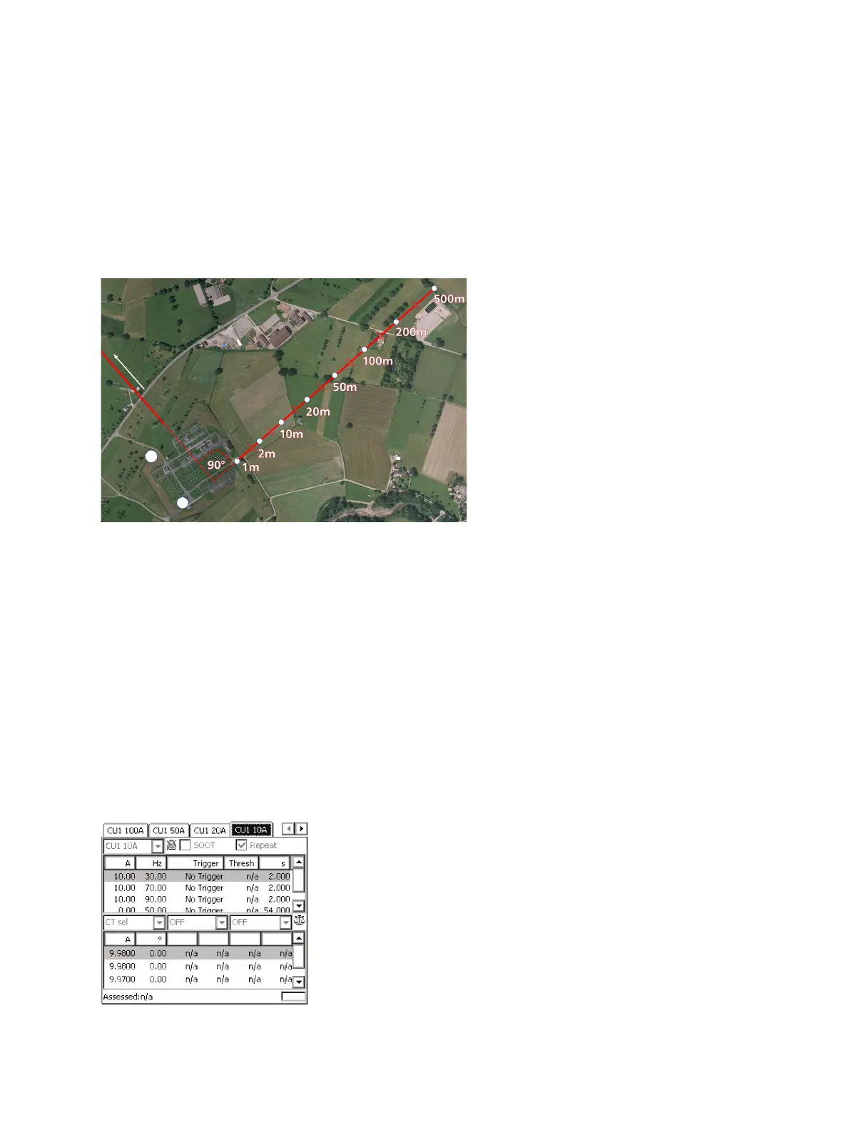
Note: In order to measure valid ground impedance values, the distance between the grounding system
under test and the remote substation must be taken into account. IEEE 81 recommends a minimum
distance of five times the maximum dimensions of the grounding system to avoid overlapping of the
ground potential rise of both the grounding system and the current probe. EN 50522 recommends a
distance of minimum 5 km, no matter the size of the grounding system.
In general, the setup must represent worst case conditions, which could occur during a single line fault.
This must be clarified for each individual grounding system.
Figure 9-2: Direction of measurement trace
According to EN 50522 and IEEE 81 the angle between the line which is used for injection and the
measurement trace must be 90° in order to avoid coupling effects, which might disturb the measurement.
In cases this is not possible due to topographical or man-made obstacles in the surroundings of the
substation, an angle of at least 60° should be maintained.
The measurement trace is realized by the use of ground rods that are placed at certain distances from
the grounding system. The following distances can be taken as a guideline: 1 m, 2 m, 5 m, 10 m, 20 m,
50 m, 100 m, 150 m, 200 m, then increase in increments of 100 m.
3. When checking the fourth criterion, use the dedicated template on the CPC 100 by following this path
in the file operations view:
Templates > Grounding Systems > PTM
4. Open the file corresponding to your power frequency and navigate to the test card matching the
current range selected on the CP CU1.
Figure 9-3: CU1 10 test card of the PTM template on the CPC 100
D
i
r
e
c
t
i
o
n
o
f
p
o
w
e
r
l
i
n
e
u
s
e
d
f
o
r
in
je
c
t
i
o
n
D
i
r
e
c
t
i
o
n
o
f
m
e
a
s
u
r
e
m
e
n
t
t
r
a
c
e

 Loading...