OMICRON 39
Ground impedance measurements with PTM
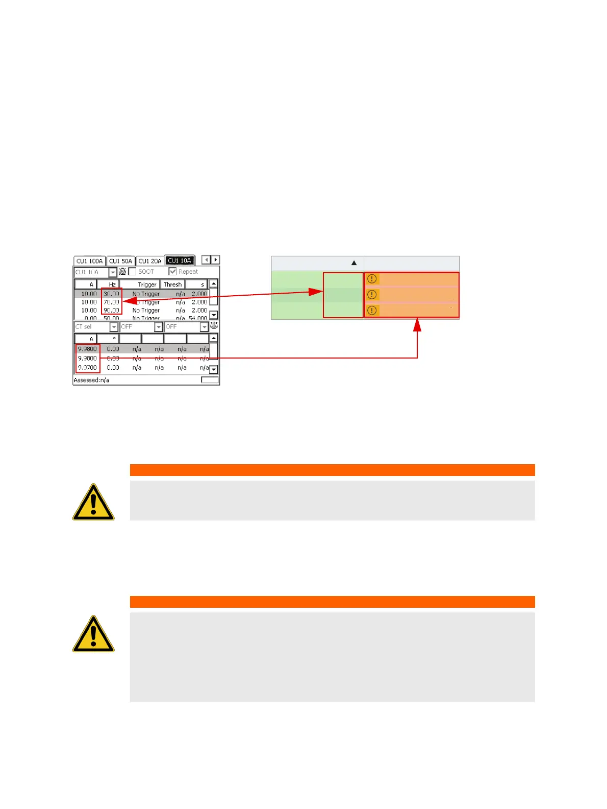
Figure 9-3 shows settings in the CU1 10 test card of the PTM template. The sequence consists of 4
states, which are applied in an endless loop, since Repeat is activated in the test card:
• Injection of the test current at 30 Hz for 2 s (measuring touch voltage at a distinct location at 30 Hz)
• Injection of the test current at 70 Hz for 2 s (measuring touch voltage at a distinct location at 70 Hz)
• Injection of the test current at 90 Hz for 2 s (measuring touch voltage at a distinct location at 90 Hz)
• No injection for 54 s (to be able to move to the next measurement location in the substation)
5. Start the injection by pressing the I/0 button on the CPC 100.
6. Start PTM on the tablet and enter the CPC 100’s current readings for each defined frequency under
Settings and Conditions. Also verify that the frequency selections in the sequencer test card and
under Settings and conditions match.
Figure 9-4: Enter the current readings under the Settings and Conditions section in PTM
7. Set the HGT1’s USB mode to COM port to enable communication with the tablet running PTM.
(Refer to 5.1 "System Settings" on page 16 for more information on how to change the USB mode).
8. Connect the HGT1 to the tablet using the HGT1’s USB connector and the delivered USB cable.
As soon as the HGT1 is recognized by PTM, it is locked and cannot be operated via its buttons any
longer.
9. Follow the examples in Figure 9-2 and Figure 9-1: on page 37, by connecting the black input of the
HGT1 with any grounded part in the substation and the red input with the rod, which is used as test
electrode.
WARNING
Death or severe injury caused by high voltage or current possible
► Never connect the HGT1 to the tablet without using the provided USB isolator.
WARNING
Death or severe injury caused by high voltage or current possible
In case of a fault, high voltage can occur at the far end of the measurement cable.
► It is recommended to unplug the test lead to the ground rod right at the HGT1’s red
input if no measurement is performed and the field crew moves to the next location.
This is to avoid transferring potential to the remote end of the test lead in the event of
a fault in the substation.
Frequency Current
30.00 Hz
70.00 Hz
90.00 Hz
A
A
A
7
9

 Loading...