5 CiA402 Drive Profile
5 - 22
EtherCAT Communication Unit USER’S MANUAL (3G3AX-MX2-ECT)
5-7 Device Profile area
This chapter explains about the supported CiA402 drive profile.
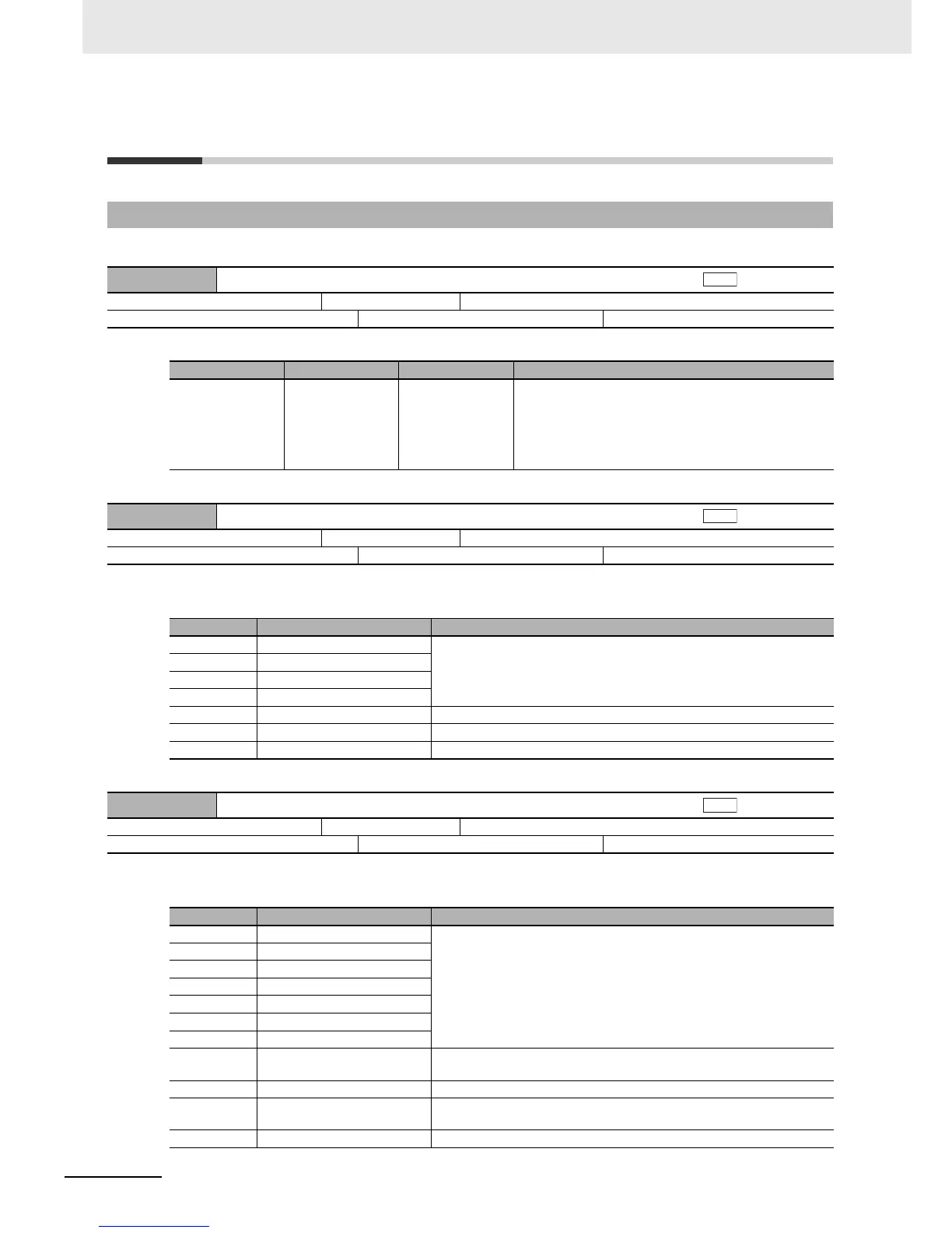
• This object gives the latest error code or warning code that occurred in the unit.
• This object controls the state transitions of the unit.
• Bit descriptions
• This object gives the present state of the unit.
• Bit descriptions
5-7-1 Drive Profile Objects
603F hex Error code
Setting range: 0000 to FFFF hex Unit: Default setting: 0000 hex
Size: 2 bytes (U16) Access: RO PDO map: Possible
Index Name Data type Specifications
603F hex Error code U16 0000 hex: No error
5300 hex: No response from the inverter
6331 hex: EEPROM data error
6341 hex: PDO setting error
FF00 hex: Warning occurred for the inverter
FF01 hex: Trip occurred for the inverter
6040 hex Controlword
Setting range: 0000 to FFFF hex Unit: Default setting: 0000 hex
Size: 2 bytes (U16) Access: RW PDO map: Possible
Bit Name Details
0 Switch on The state is controlled by these bits.
Quick stop is not supported. Even when the bit 2 is set to 0, it is ignored.
For details, refer to 5-1-3 Command Coding on page 5-3.
1 Enable voltage
2 Quick stop
3 Enable operation
4 to 6 Reserved Not used. Always keep at 0.
7 Fault reset Faults and warnings are cleared when this bit turns ON.
8 to 15 Reserved Not used. Always keep at 0.
6041 hex Statusword
Setting range: 0000 to FFFF hex Unit: Default setting: 0000 hex
Size: 2 bytes (U16) Access: RO PDO map: Possible
Bit Name Details
0 Ready to switch on These bits give the state.
For details, refer to 5-1-4 State Coding on page 5-3.
1 Switched on
2 Operation enabled
3 Fault
4 Voltage enabled
5 Quick stop
6 Switch on disabled
7 Warning 0: No warning occurred for the unit or inverter.
1: Warning occurred for the unit or inverter.
8 Reserved Not used.
9 Remote 0: Control from Controlword is disabled.
1: Indicates that control is being performed by Controlword.
10 to 15 Reserved Not used.