4 - 5
4 Inverter Control
EtherCAT Communication Unit USER’S MANUAL (3G3AX-MX2-ECT)
4-2 Control with the Position Control Unit
4
4-2-3 Control Method
Control the inverter by operating the fixed mapping PDOs.
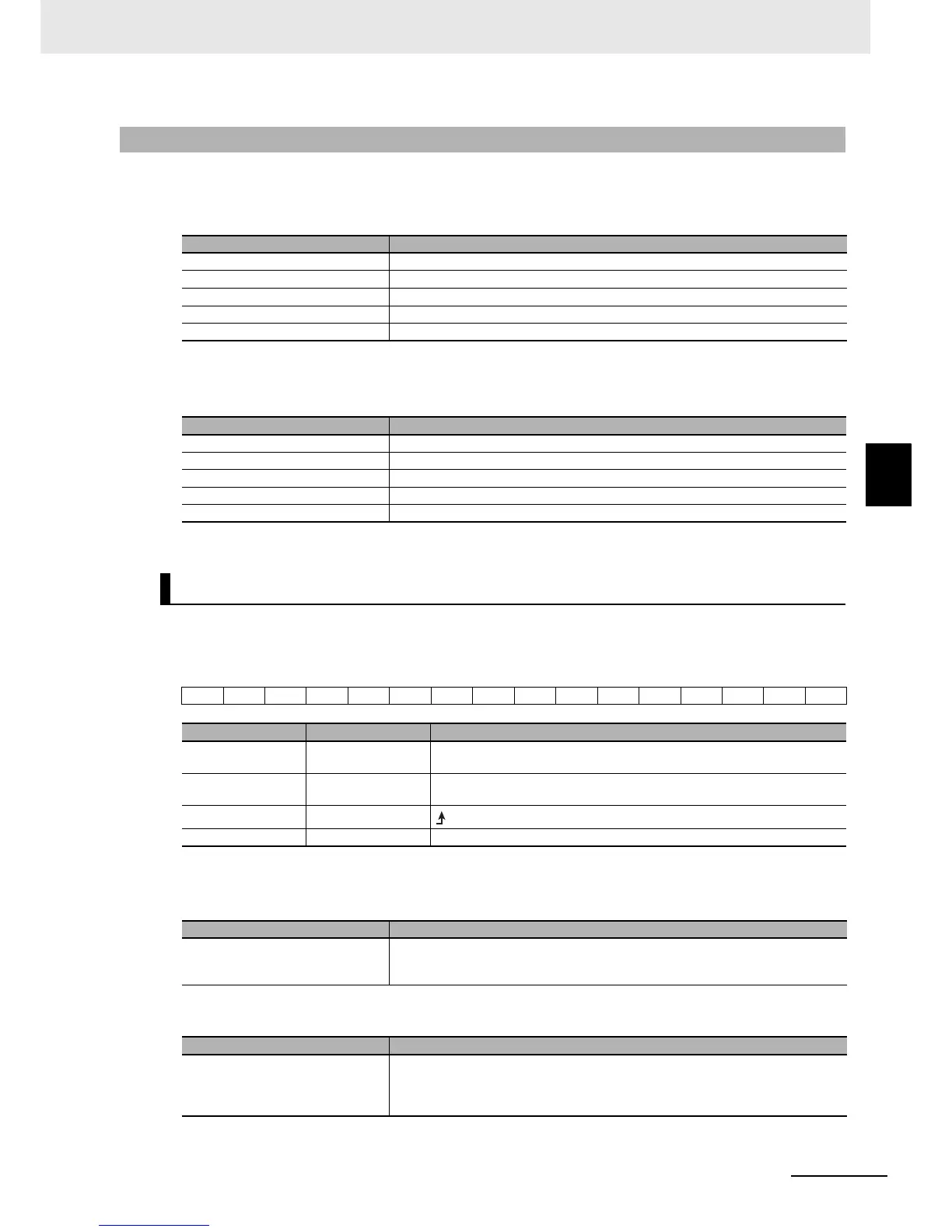
Control information (master to slave)
(Notes) n: Start address of the remote I/O output relay area that is assigned to the unit.
Status information (slave to master)
(Notes) m: Start address of the remote I/O input relay area that is assigned to the unit.
Command
The bit data for the command is shown below.
*1 Operates as a start bit when Simple position control is enabled.
Frequency reference
Multi-step Position command 0
4-2-3 Control Method
Word Meaning
n Control command
n + 1 Frequency reference
n + 2 Multi-step position command 0 (LSW)
n + 3 Multi-step position command 0 (MSW)
n + 4 Multi-function input
Word Meaning
m Status
m + 1 Output frequency monitor
m + 2 Current position monitor (LSW)
m + 3 Current position monitor (MSW)
m + 4 Multi-function output monitor
Bit and data information
7 10
Bit Name Meaning
0 Forward/stop *10: Stop
1: Forward command
1 Reverse/stop *10: Stop
1: Reverse command
7 Fault reset
: Resets an error or trip for the unit or inverter.
- (Reserved) The reserved area. Set 0.
Name Meaning
Frequency reference Specify the reference frequency in increments of 0.01 Hz. When a value is set that
exceeds the maximum frequency, operation is performed at the maximum frequency.
Setting range: 0 to maximum frequency
Name Meaning
Multi-step position command 0 Specify the value of inverter parameter P060: Multi-step position command 0. Values
outside the range are not applied and operation is performed with the previous value.
Setting range: Position range setting (reverse side) to position range setting (forward
side)