4 Inverter Control
4 - 6
EtherCAT Communication Unit USER’S MANUAL (3G3AX-MX2-ECT)
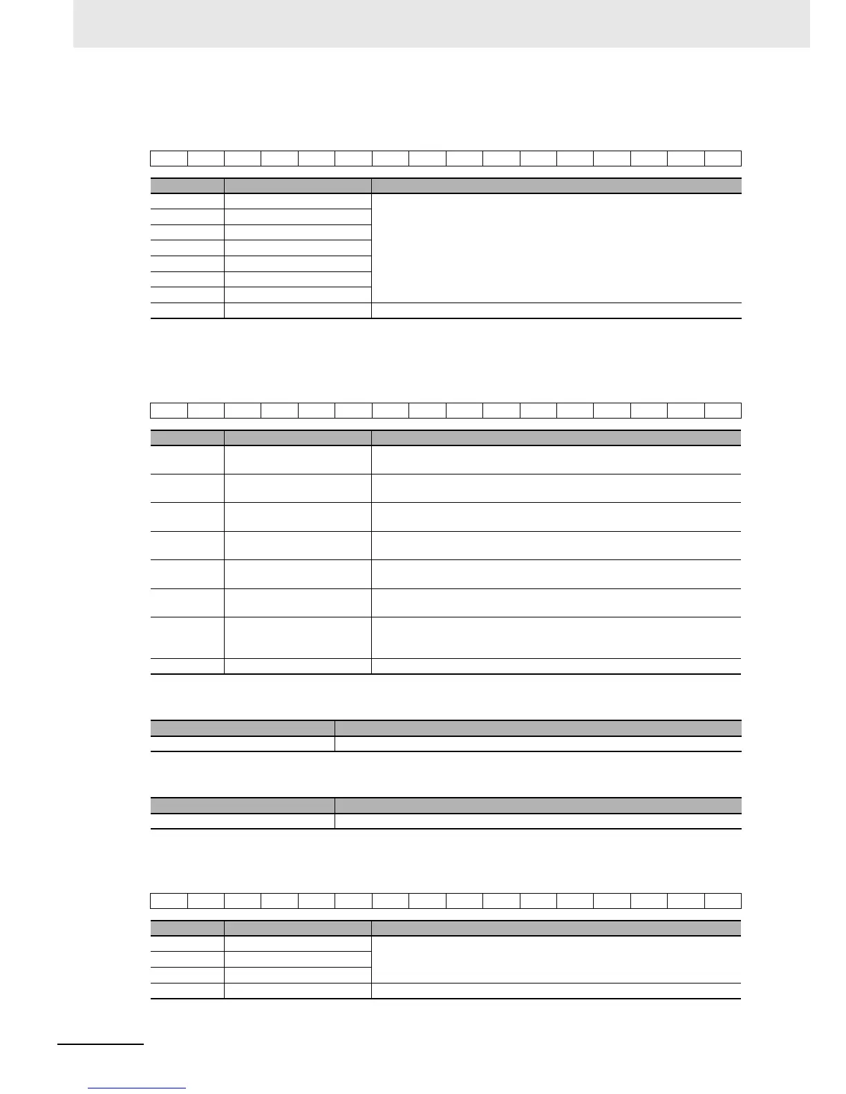
Multi-function input
The bit data for the multi-function input information is shown below.
* Use by assigning a function to the multi-function input with the inverter parameters.
Status
The bit data for the status information is shown below.
Output frequency monitor
Current position monitor
Multi-function output monitor
The bit data for the multi-function output monitor information is shown below.
* Use by assigning a function to the multi-function output with the inverter parameters.
13 12 11 10 9 8 7
Bit Name Meaning
7 Multi-function input 1 0: OFF
1: ON
8 Multi-function input 2
9 Multi-function input 3
10 Multi-function input 4
11 Multi-function input 5
12 Multi-function input 6
13 Multi-function input 7
(Reserved) The reserved area. Set 0.
15 12 9 7 3 10
Bit Name Meaning
0 Forward operation in
progress
0: Stopped/during reverse operation
1: During forward operation
1 Reverse operation in
progress
0: Stopped/during forward operation
1: During reverse operation
3 Fault 0: No error or trip occurred for the unit or inverter
1: Error or trip occurred for the unit or inverter
7 Warning 0: No warning occurred for the unit or inverter
1: Warning occurred for the unit or inverter
9 Remote 0: Local (Operations from EtherCAT are disabled)
1: Remote (Operations from EtherCAT are enabled)
12 Frequency matching 0: During acceleration/deceleration
1: Frequency matched
15 Connection error between the
Optional Unit and inverter
0: Normal
1: Error (Cannot update data for the inverter. To restore, turn the power OFF
and then ON again.)
(Reserved) The reserved area. Set 0.
Name Meaning
Output frequency monitor Displays the output frequency in increments of 0.01 Hz.
Name Meaning
Current position monitor Displays the value of inverter parameter d030: Current position monitor.
6 10
Bit Name Meaning
0 Multi-function output P1/EDM 0: OFF
1: ON
1 Multi-function output P2
6 Multi-function relay output
(Reserved) The reserved area. Set 0.