2 - 17
2 Starting a Sample System
EtherCAT Communication Unit USER’S MANUAL (3G3AX-MX2-ECT)
2-5 Mounting and Wiring for the EtherCAT
Communication Unit
2
2-5-3 Wiring Conforming to EMC Directives
To conform to the EMC directives (EN61800-3), conduct the wiring work for the EtherCAT
Communication Unit, so that it meets the wiring conditions described in this section. These conditions
are for conformance of products to the EMC directives when an EtherCAT Communication Unit is
installed on a SYSDRIVE MX2-series inverter. The installation and wiring conditions, however, may be
affected by the devices that are connected and wiring of the system where the EtherCAT
Communication Unit is installed. It is necessary to conform to the EMC directives as an overall system.
This section describes only the parts related to the addition of the EtherCAT Communication Unit.
Follow the instructions in the inverter manual for the inverter installation conditions, such as the power
supply line wiring, filter installation, and motor wiring clamps.
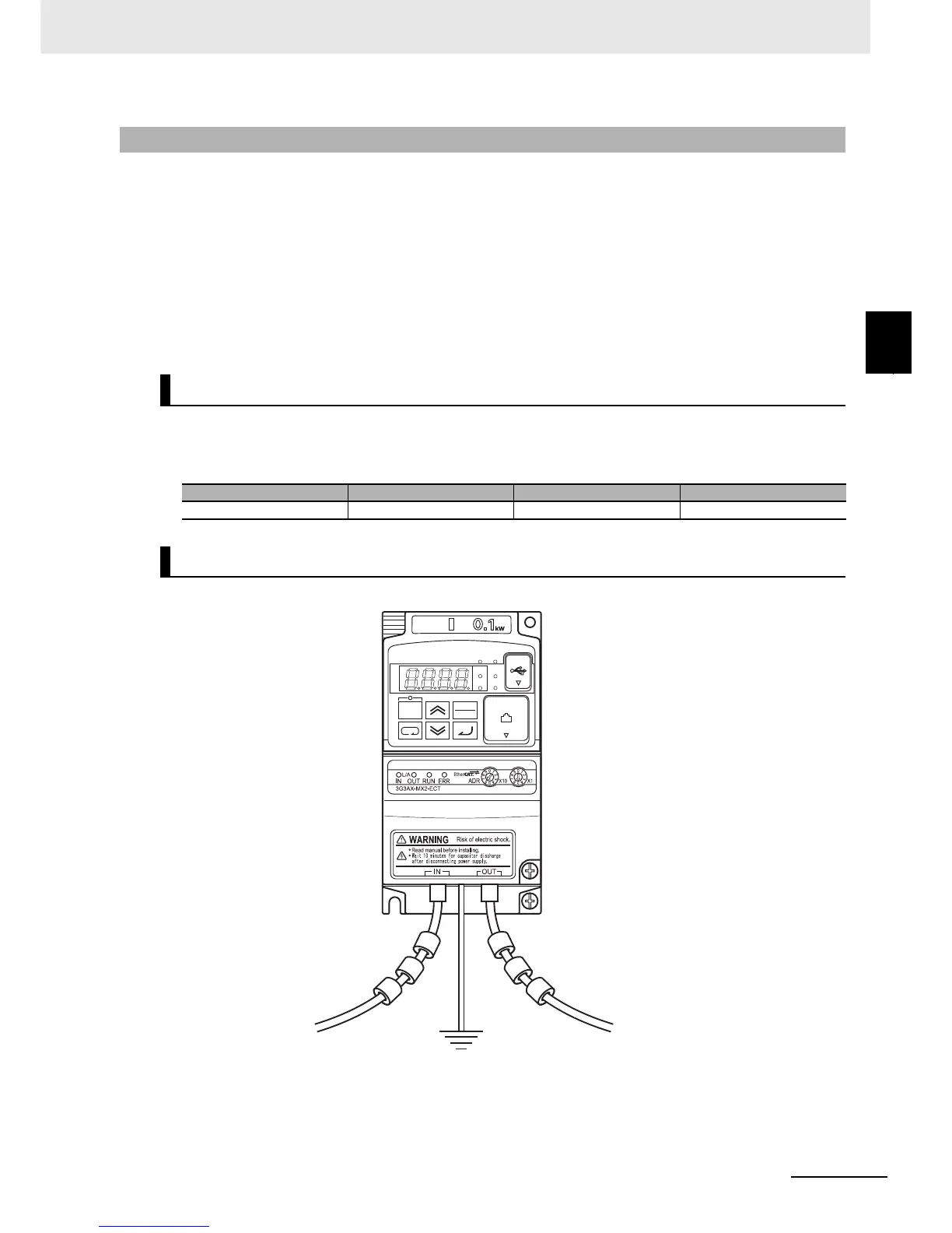
Install the 3 clamp cores shown below near the communications connectors of the communications
cables that are connected to the communications connector (IN) and the communications connector
(OUT). (If the communications cable on the OUT side is not connected, install them for the IN side only.)
Install the FG cable with the shortest possible wiring.
(Notes) The overall mounting appearance varies depending on the inverter capacity. Do not squeeze
the FG cable into the EtherCAT Communication Unit.
2-5-3 Wiring Conforming to EMC Directives
Wiring the communications cables
Symbol Name Manufacturer Model
FC1, FC2, FC3 Clamp core NEC TOKIN ESD-SR-160
Wiring the FG cable