2 Installation and connection
2-3 Connecting the equipment
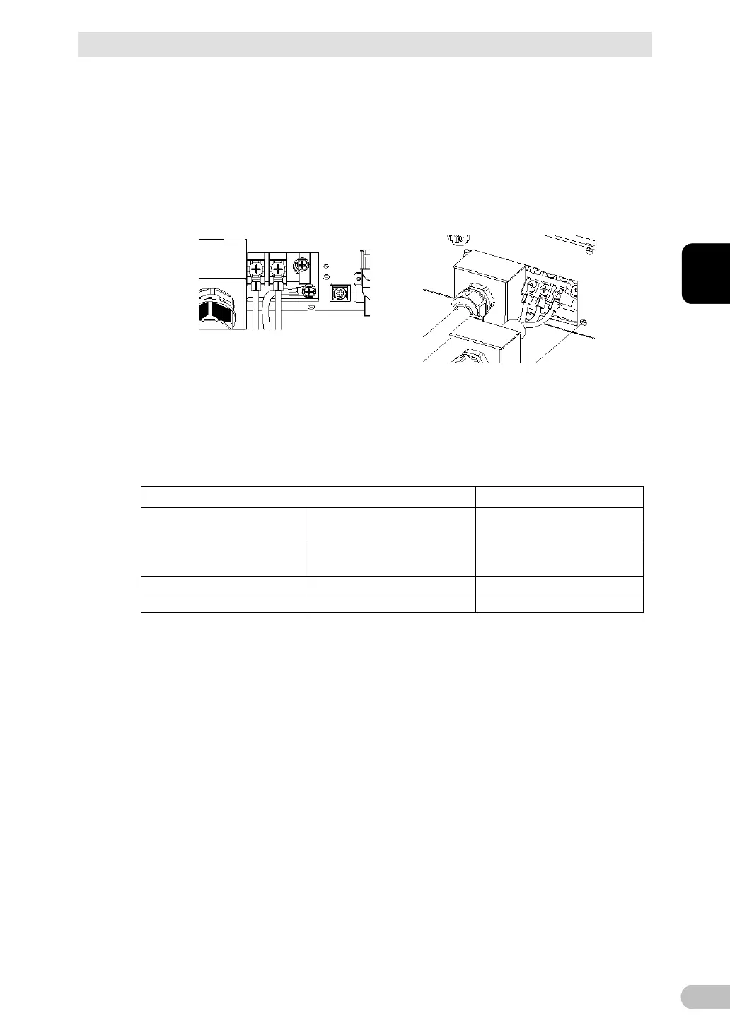
BU5002R/BU3002R/BU3002RH
Loosen the screw on the terminal block using a screwdriver, insert the wire, and
tighten the screw on the terminal block.
The wire to be connected to the G terminal should be longer than the wires to be
connected to L1 and L2.
See Table 1 for the wire size to be used.
When installing the G terminal of the
BU5002R, pass it below the L1 and
L2 wires, and arrange the wiring
horizontally.
G terminal: Connect to earth wire
L1 terminal: Connect to line wire
L2 terminal: Connect to neutral wire
O.D.: Less than 12.7mm
I.D.: M5
O.D.: Less than 9.6 mm
I.D.: M4
Clamp recommended
wiring external size