34
Instance Specifications Section 2-2
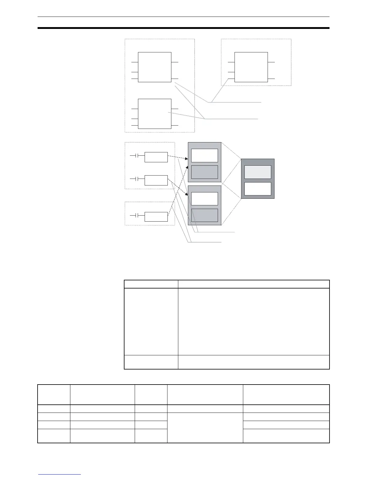
2-2-2 Parameter Specifications
The data that can be set by the user in the input parameters and output
parameters is as follows:
Note (1) The following table shows the methods for inputting values in parameters.
CTD
CD Q
LD
PV CV
D100
CTD
CD Q
LD
PV CV
D200
CTD
CD Q
LD
PV CV
D150
FB
FB
FB
Program 1 (automatic operation)
Program 2 (manual operation)
Product A counter
Product B counter
Product B counter
Program 1
Instance A
Instance B
Program 2
Instance A
Reading the same product’s counter
value at different locations
Reading different products’ counter values
(Algorithm calculating counter value is the same.)
Use the same internal variables
Use different internal variables
Instance A
Instance B
I/O variables,
Internal
variables
Body
I/O variables,
Internal
variables
Body
FB definition
Variable
definitions
Body
Item Applicable data
Input parameters Values (See note 1.), addresses, and program symbols (glo-
bal symbols and local symbols) (See note 2.)
Note The data that is passed to the input variable from the
parameter is the actual value of the size of the input
variable data. (An address itself will not be passed even
if an address is set in the parameter.)
Note Input parameters must be set. If even one input param-
eter has not been set, a fatal error will occur and the
input parameters will not be transferred to the actual
PLC.
Output parameters Addresses, program symbols (global symbols, local symbols)
(See note 2.)
Input
variable
data type
Contents Size Parameter value input
method
Setting range
BOOL Bit data 1 bit P_Off, P_On 0 (FALSE), 1 (TRUE)
INT Integer 16 bits Positive value: & or + followed
by integer
Negative value:
− followed by
integer
−32,768 to 32,767
DINT Double integer 32 bits −2,147,483,648 to 2,147,483,647
LINT Long (8-byte) integer 64 bits −9,223,372,036,854,775,808 to
9,223,372,036,854,775,807