58
Alarm Hysteresis Section 4-2
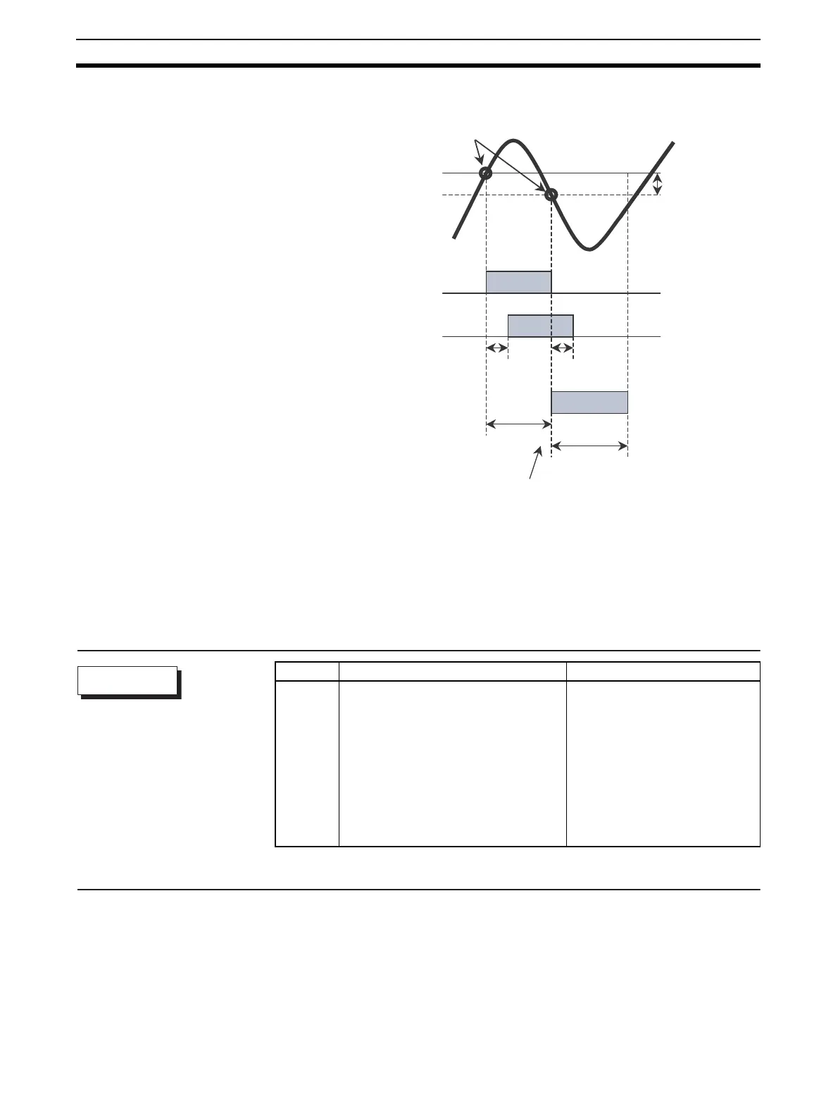
The following figure shows an example of absolute-value upper-limit alarms to
illustrate the effect of delay function on alarm output.
Note 1. During a delay, the alarm display and communications status will also be de-
layed.
2. During a delay, if an alarm ON/OFF status changes, delay will occur again.
3. When power is turned on, or the initial setting level changes to the operation
level, the ON delay will be used.
4. All outputs will turn OFF and the OFF delays will not function when moving
to the initial setting level or when an alarm is output for a heater burnout er-
ror.
@:1, 2, or 3
T
ON Delay
OFF Delay
T
T
1
t
11
T
2
t
21
t
22
t
21
>T
ON Delay
OFF Delay
t
12
Example)
Absolute-value Upper-limit Alarm
Hysteresis Amoun
Prevents Frequent
Switching.
PV
Alarm Value
Alarm Output
(no delay feature)
Alarm Output
(with delay)
Alarm Output
(with delay)
Condition Switching Point
During a delay, if an alarm ON/OFF status changes, delay will occur again.
≤
t
11
Symbol Parameter Level Description
alh
@
Alarm 1 to 3 hysteresis:
Advanced Function Setting Level
Alarm
rest Standby Sequence Reset:
Advanced Function Setting Level
Alarm
al
@n
Alarm 1 to 3 Open in Alarm:
Advanced Function Setting Level
Alarm
a
@on
Alarm 1 to 3 ON delay:
Advanced Function Setting Level
Alarm
a
@of
Alarm 1 to 3 OFF delay:
Advanced Function Setting Level
Alarm
Parameters