54
Chapter3 Mounting
F3SJ-B
User’s Manual
Wiring/Installation
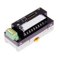
5.
Tighten the screws to mount to the wall by the order of Top/Bottom and Intermediate Brackets. (Figure 11)
Screws to mount the brackets to the wall are not included.
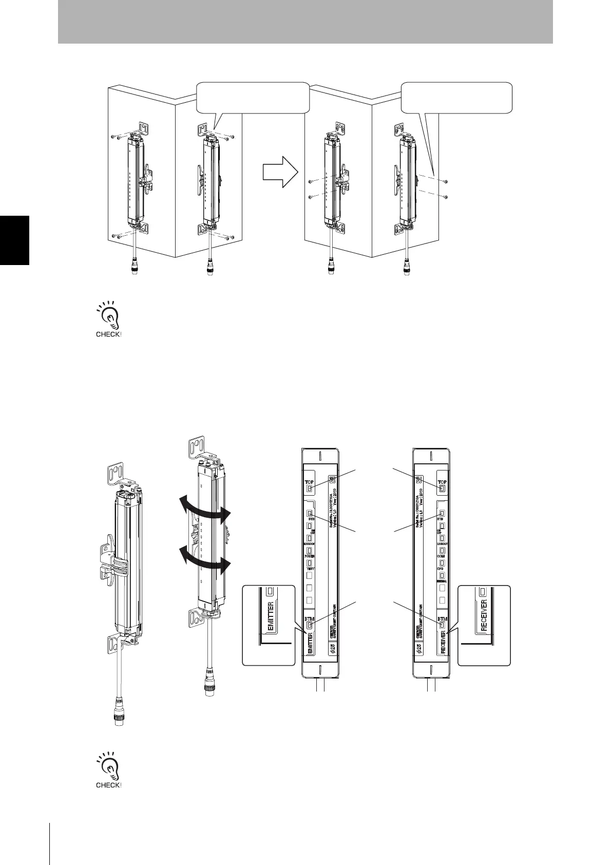
6. Turn ON the sensor to perform beam alignment.
Move the emitter from side to side (
Figure 12
) to align it to a center position where the stable-state
indicator (STB) is turned ON while checking the top beam state and bottom beam state with the top-
beam-state indicator (TOP) and bottom-beam-state indicator (BTM). (
Figure 13
)
Next, move the receiver from side to side to align it to a center position where the stable-state indicator
(STB) is turned ON. (
Figure 13
)
- Confirm that there is no interrupting object in the detection zone before adjusting beams.
- If the stable-state indicator (STB) does not turn ON despite performing alignment, check if the mounting surfaces of
the emitter/receiver are parallel, and if the mounting height of the emitter/receiver is appropriate. Using optional
Laser Alignment Kit (F39-PTJ) makes alignment easier.
Tighten the screws to secure
the Intermediate Bracket (3)
and the wall.
Tighten the screws to secure
the Top/Bottom Brackets
and the wall.
Emitter Receiver
TOP indicator
(Blue)
STB indicator
(Green)
BTM indicator
(Blue)
RECEIVER
EMITTER

 Loading...