Displayed item Description
The number of application proc-
ess
Differs depending on the Sensor Controller mode. Refer to 4-4 Set-
ting Operation Mode [Startup Settings] on page 4 - 11.
Standard = 1
Double Speed Multi-input = 2
Non-stop adjustment = 2 (Operation: Process 0, Adjustment: Proc-
ess 1)
Multi line random trigger mode = Number of set lines (Each line
number corresponds to the process number).
Physical memory (the remaining
capacity/total capacity)
The remaining capacity and total capacity of the Physical memory
installed in the Sensor Controller.
Unit + Image Inclusive sum Total size of unit that is held by the scene group loaded to the Sen-
sor Controller and image data.
Virtual Available (MB) Amount of virtual memory usable.
2GB is applied to each application process. For the FH-2000/5000
series, 8TB is applied to each application process.
This memory region can be temporary used by application process.
If you check the remaining capacity, you can confirm the operating
status. Users can not access to this memory.
Unit(MB) Total data size of the units held by Scene groups that are loaded to
the Sensor Controller.
Image(MB) Total data size of the image data held by Scene groups that are
loaded to the Sensor Controller.
2
Click the Close button.
Additional Information
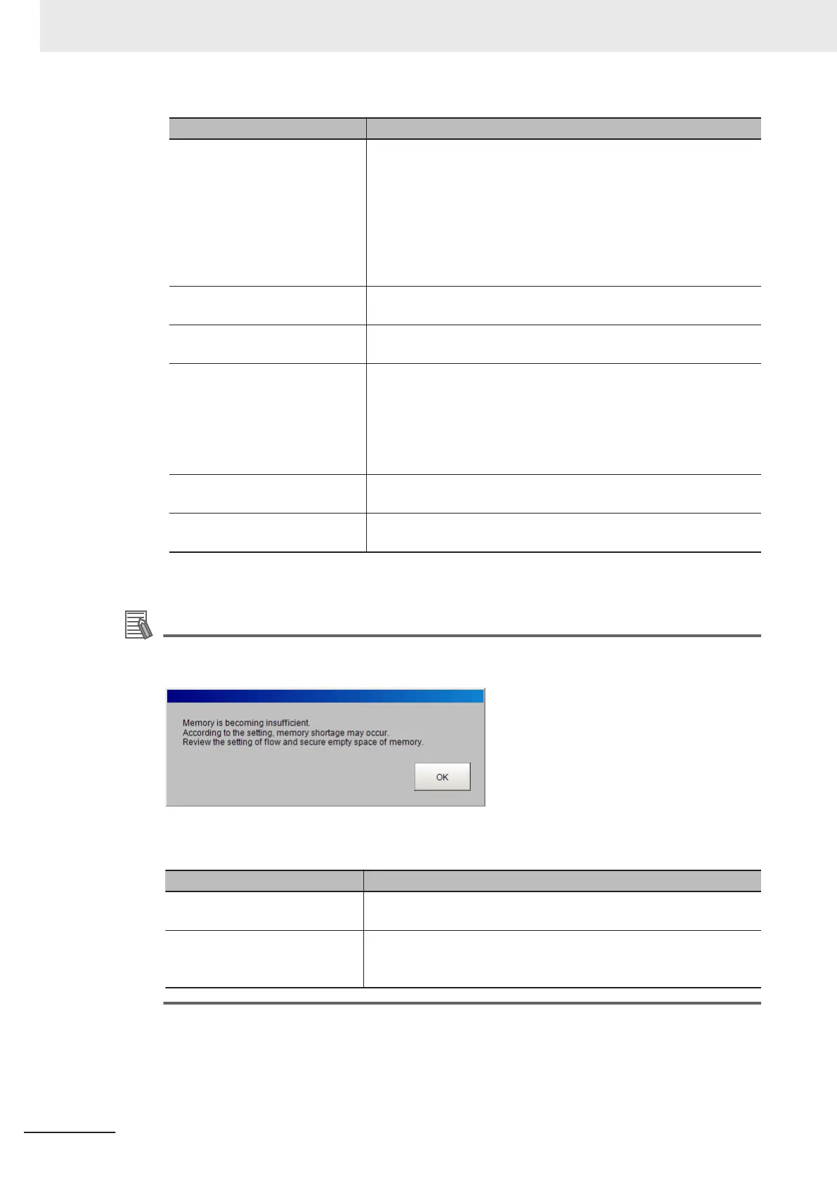
With FH/FHV series, when the amount of memory used in the Sensor Controller exceeds a cer-
tain level, The following warning message dialog will be displayed.
If this dialog is displayed, check the memory status and take the following measures to enlarge
the Virtual Available (MB).
Status Countermeasures
Unit value it too large. Modify the Scenes and reduce the number of processing items. Or
split the Scene group.
Image value is too large. Modify the Scenes and reduce the filter units.
Replace some filtering processing into one advanced filter.
Or lower the camera resolution.
3 Basic Operations
3 - 26
FH/FHV Series Vision System User’s Manual (Z365-E1)

 Loading...


