1.5 Nomenclature
1-13
OUTLINE
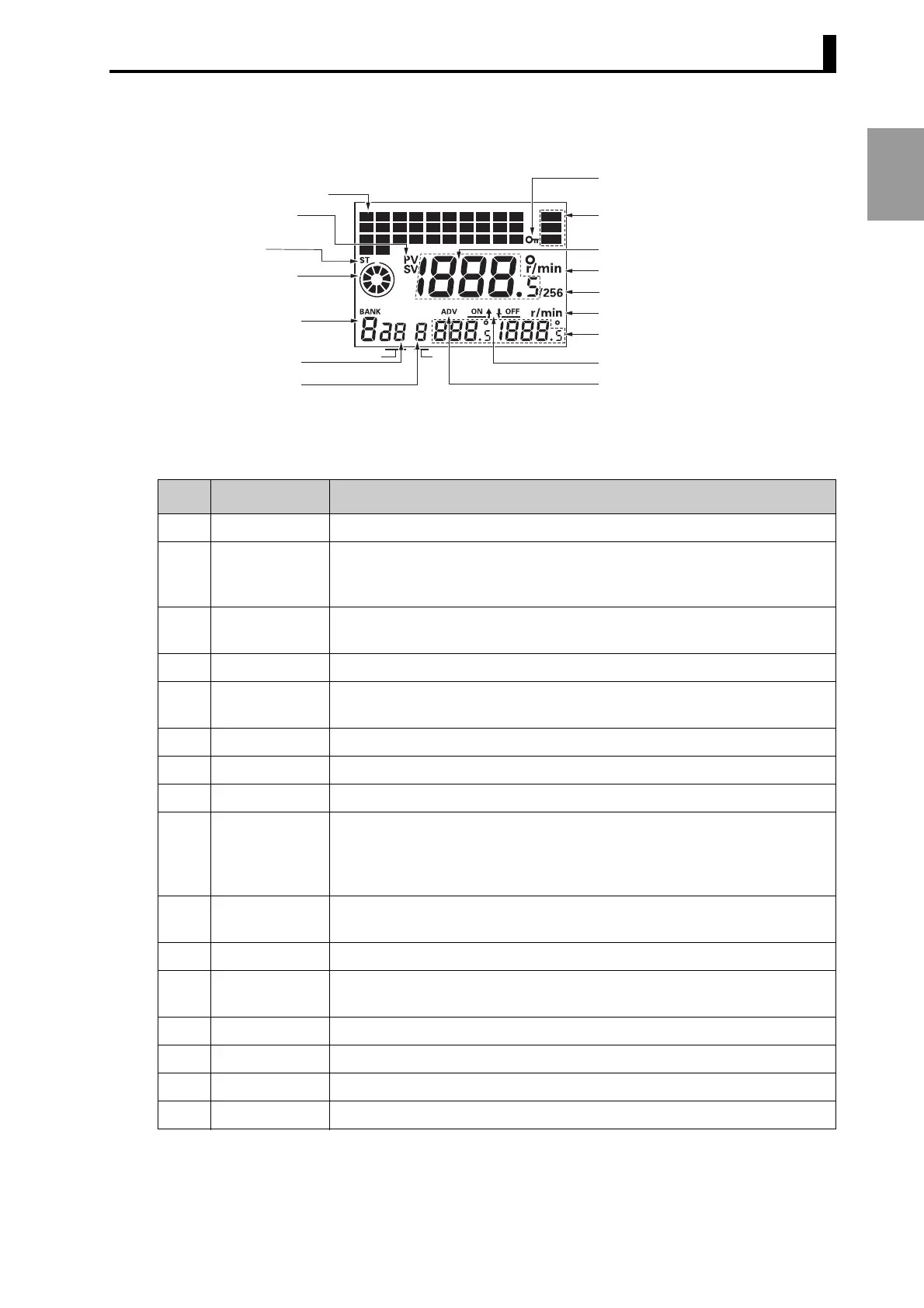
● Displays
* The illustration above shows the display section of a 32-output model.
16-output models have an output display covering 1 to 16 only.
CAM
STEP
(3) Start input
indication
(5) Bank No. display
(2) PV/SV indicator
(4) Rotation display
monitor
(6) Cam No. display
(7) Step No. display
(8) All protect indication
(9) Mode indicator
(10) Main display
(11) Unit indication
(13) Unit indication
(12) 256 indication
(14) Sub-display
(15) ON/OFF indication
(16) ADV indication
12345678910
PRG
TST
RUN
11 12 13 14 15 16 17 18 19 20
21 22 23 24 25 26 27 28 29 30
31 32
(1) Cam output indicator
No. Display color Description
(1) Orange Lit while cam outputs are ON.
(2) Red PV: Lit while the present angular position or speed is displayed in Main
display.
SV: Lit while the setting value is displayed in Main display.
(3) Orange Lit while the start input is ON in Run or Test Mode.
Not lit when an error occurs.
(4) Orange
Displays Encoder present angular position, direction, and speed guidelines.
(5) Green Displays the bank number that is running in Run or Test Mode and the
bank number selected in Programming Mode.
(6) Green Displays the cam number for the angle setting displayed on Sub-display.
(7) Green Displays the step number for the angle setting displayed on Sub-display.
(8) Orange Lit while the All Protection function is enabled.
(9) Orange The indicator for the selected mode is lit.
PRG: Programming Mode
TST: Test Mode
RUN: Run Mode
(10) Red Displays the present angular position or the speed and settings being
made.
(11) Red Displays units for the angle or the speed displayed on Main display.
(12) Red Lit while using an Encoder with a resolution of 256 if 256° display is
selected.
(13) Green Displays units for the angle or the speed displayed on Sub-display.
(14) Green Displays the speed or the ON/OFF angle settings.
(15) Green Indicates whether Main display displays the ON or OFF angle setting.
(16) Green Lit while setting the Advance Angle Compensation (ADV) Function.