Section 2 INSTALLATION
2-4
INSTALLATION
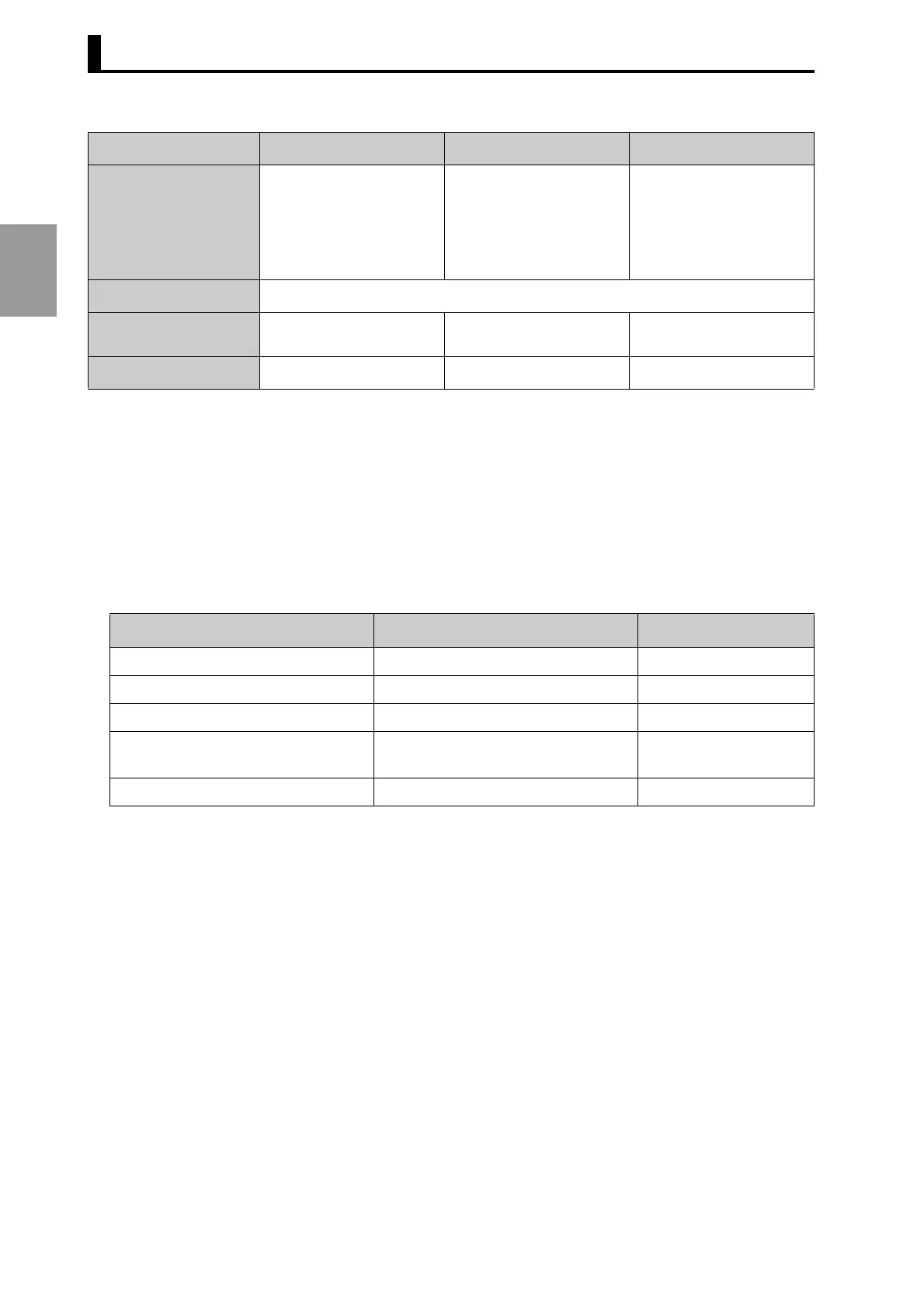
*1: The rush current indicated below will flow when the power is switched on.
Model E6CP-AG5C-C: Approx. 8 A (Time: Approx. 0.3 ms)
Model E6C3-AG5C-C: Approx. 6 A (Time: Approx. 0.8 ms)
Model E6F-AG5C-C: Approx. 9 A (Time: Approx. 5 µs)
*2: JEM1030: Applied in 1991
■ Options
* Ask your OMRON representative about the availability of non-standard lengths.
Vibration resistance
Destruction:
10 to 55 Hz,1.5-mm dou-
ble amplitude for 2 hr each
in X, Y, and Z directions
Destruction:
10 to 500 Hz, 2-mm double
amplitude, 150 m/s
2
3
times each in X, Y, and Z
directions, 11-min sweep
time
Destruction:
10 to 500 Hz,1.5-mm dou-
ble amplitude 3 times each
in X, Y, and Z directions,
11-min sweep time
Shock resistance
Destruction: 1,000 m/s
2
3 times each in X, Y, and Z directions
Weight
Approx. 200 g
(with 2-m cord)
Approx. 300 g
(with 1-m cord)
Approx. 500 g
(with 2-m cord)
Datasheet Cat. No.
---
F058 E283
Name Specifications Model
Shaft Coupling for the E6CP Axis: 6 mm dia. E69-C06B
Shaft Coupling for the E6C3 Axis: 8 mm dia. E69-C08B
Shaft Coupling for the E6F Axis: 10 mm dia. E69-C10B
Extension Cable (*) 5 m
(same for E6CP, E6C3, and E6F)
E69-DF5
Parallel Input Adapter Two Units can operate in parallel. Y92C-30
Item E6CP-AG5C-C E6C3-AG5C-C E6F-AG5C-C