94
Connecting to the RS-232C Port at the Host
Section 4-1
Wiring for a Memory Link connection
Cables with connectors that can be used at serial port A:
CV500–CN228 (9–pin⇔25–pin, 2 m)
XW2Z–S002 (9–pin⇔9–pin, 2 m)
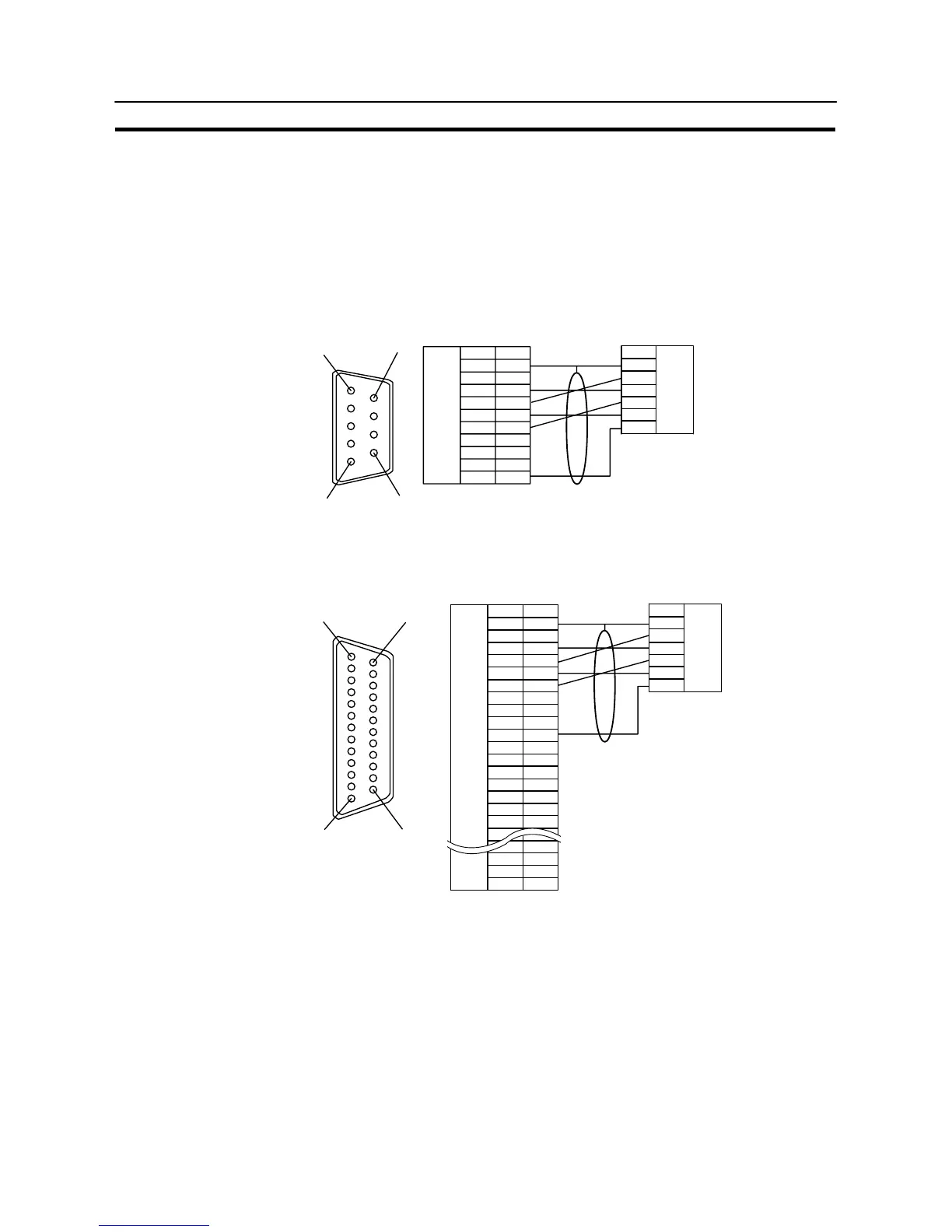
[Serial port A]
Prepare the adapter cable while referring to the following diagram.
(9-pin type)
Shielding wire
1
6
5
9
Abbreviation
FG
−
SD
RD
RS
CS
+5V
−
−
SG
Pin number
Connector
hood
1
2
3
4
5
6
7
8
9
RS-232C
connector
RS-232C
connector
Abbreviation
Connector
hood
SD
RD
RS
CS
SG
NT31/NT31C
PC (Host link unit)
Serial port B
Prepare the adapter cable while referring to the following diagram.
114
13 25
NT31/NT31C
FG
CS
RS
RD
SD
TRM
–
–
SG
–
–
SDA (–)
RDA (–)
–
RDB (+)
SDB (+)
–
–
–
RSB (+)
RSA (–)
1
2
3
4
5
6
7
8
9
10
11
12
13
14
15
16
–
23
24
25
–
(25-pin type)
RS-232C
/422A/485
connector
Abbreviation
Pin number
Connector
hood
Shielding wire
RS-232C
connector
Abbreviation
Connector
hood
SD
RD
RS
CS
SG
PC (Host link unit)