6
7
8
9
1
2
3
4
5
659
Using an RS-232C/RS-422A Convertor Unit
APPENDIX C
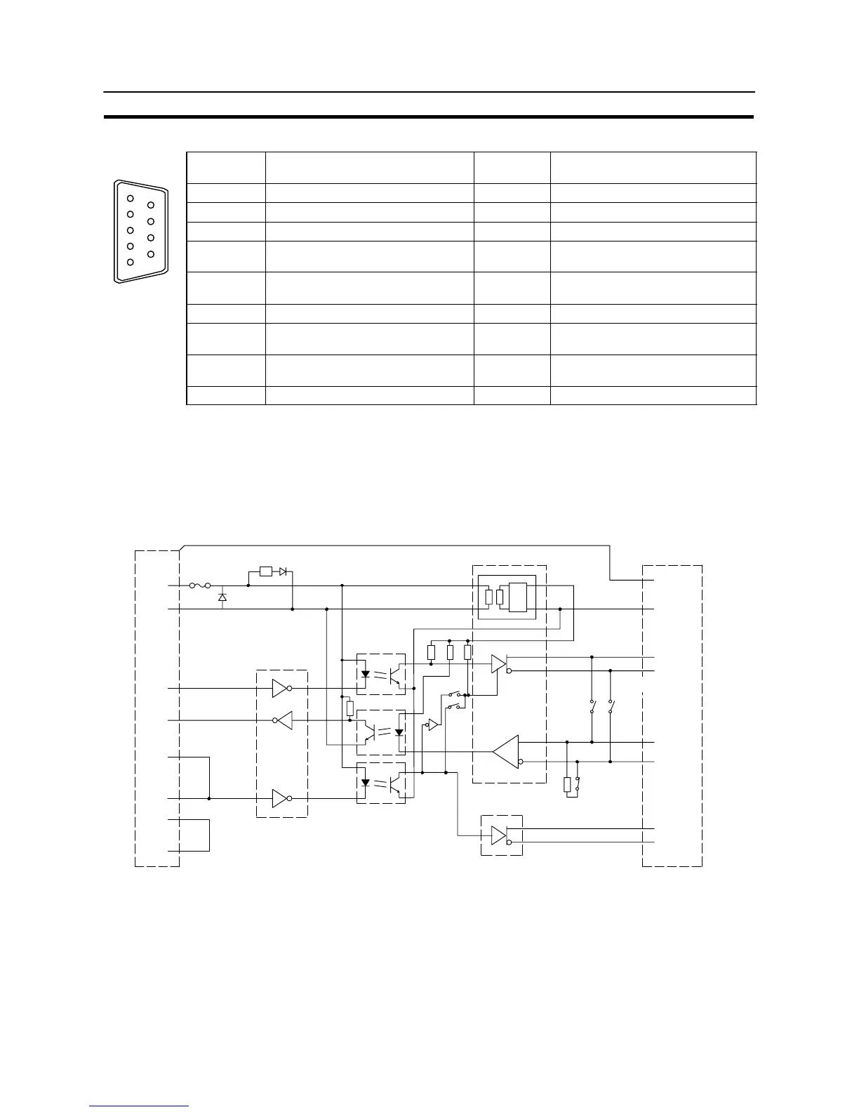
RS-232C Connector
Connector
pin No.
Signal name Abbreviation
Signal direction
(convertor unit ⇔ RS-232C device)
1 Not used – –
2 Send data SD ←
3 Receive data RD →
4 Request to send
(shorted to CS internally)
RS ←
5 Clear to send
(shorted to RS internally)
CS →
6 +5 V (150 mA) input for convertor unit +5 V →
7 Data set ready
(shorted to ER internally)
DR →
8 Data terminal ready
(shorted to DR internally)
ER ←
9 Signal ground SG –
* The hood is connected to the functional ground terminal of the RS-422A terminal block.
Block Diagram
A diagram showing the internal blocks of the convertor unit is shown below. Refer to this diagram when making
cables yourself, or when connecting devices with special interfaces.
SW1-6
Terminator
R
R
D-SUB 9P CASE
+5 V
SG
SD
RD
RS
CS
DR
ER
6
9
2
3
4
5
7
8
POWER
LED
RS-232C
Dr/Rec
RS-422A/485 Dr/Rec
DC-DC
IS_5 V
IS_0 V
FG
1
2
3
4
6
5
7
8
SW1-5
SW1-4
SG
SDB
SDA
RDB
RDA
CSB
CSA
SW1-2
RS–422A Dr
SW1-3
RS-232C side
Fuse
Convertor
RS-422A/485 side
8P terminal block
Photocoupler
2-wire type/
4-wire type
RR
R
R
L L REG