133
Connecting to the Host’s RS-422A/485 Port
Section 5-2
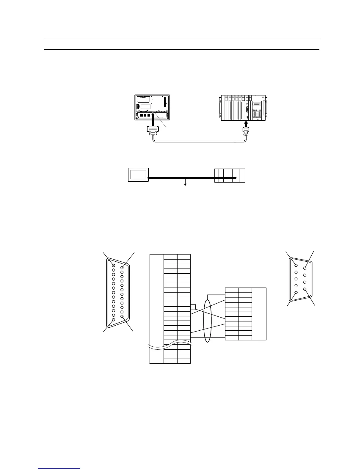
5-2-2 Direct Connection between RS-422A Ports at Both Units
The connection method in which the RS-422A ports of an NT31/NT31C and a host
are connected is described here.
NT31/NT31C
Host link/CPU/
Communication unit
SYSMAC
CS1 series PLC,
C series PLC,
CVM1/CV series
PLC, SRM1
9-pin connector
or 25-pin connector
Serial port B
(RS-422A, 25-pin type)
25-pin
connector
RS-422A cable with connectors (max. length: 500m)
Connecting an NT31/NT31C and Host (RS-422A)
NT31/NT31C
RS-422A
Host
Wiring when connecting a C-series host link unit or CPM1 (host link)
Applicable units:
C200H-LK202-V1
3G2A5-LK201-EV1
C500-LK203
3G2A6-LK202-EV1
1
14
13 25
NT31/NT31C side
Shielding wire
(25-pin type)
Abbreviation
FG
−
SD
RD
RS
CS
−
SG
−
TRM
RDB (+)
SDB (+)
−
−
−
SDA (−)
RDA (−)
−
−
RSB (+)
RSA (−)
−
Pin number
Connector
hood
1
2
3
4
5
6
7
8
9
10
11
12
13
14
15
16
−
23
24
25
RS-232C/
422A/485
connector
6
5
9
1
PC side
RS-422A
connector
Pin number
Connector
hood
1
2
3
4
5
6
7
8
9
Abbreviation
FG
RDB
−
−
−
SDB
RDA
FG
−
SDA
(9-pin type)
In order to avoid an FG ground loop, do not connect the functional ground of the
NT31/NT31C to the shielding of the RS-422A cable.