58
Using a Memory Unit (NT31/NT31C without V1)
Section 3-6
3-6-1 Installation Method
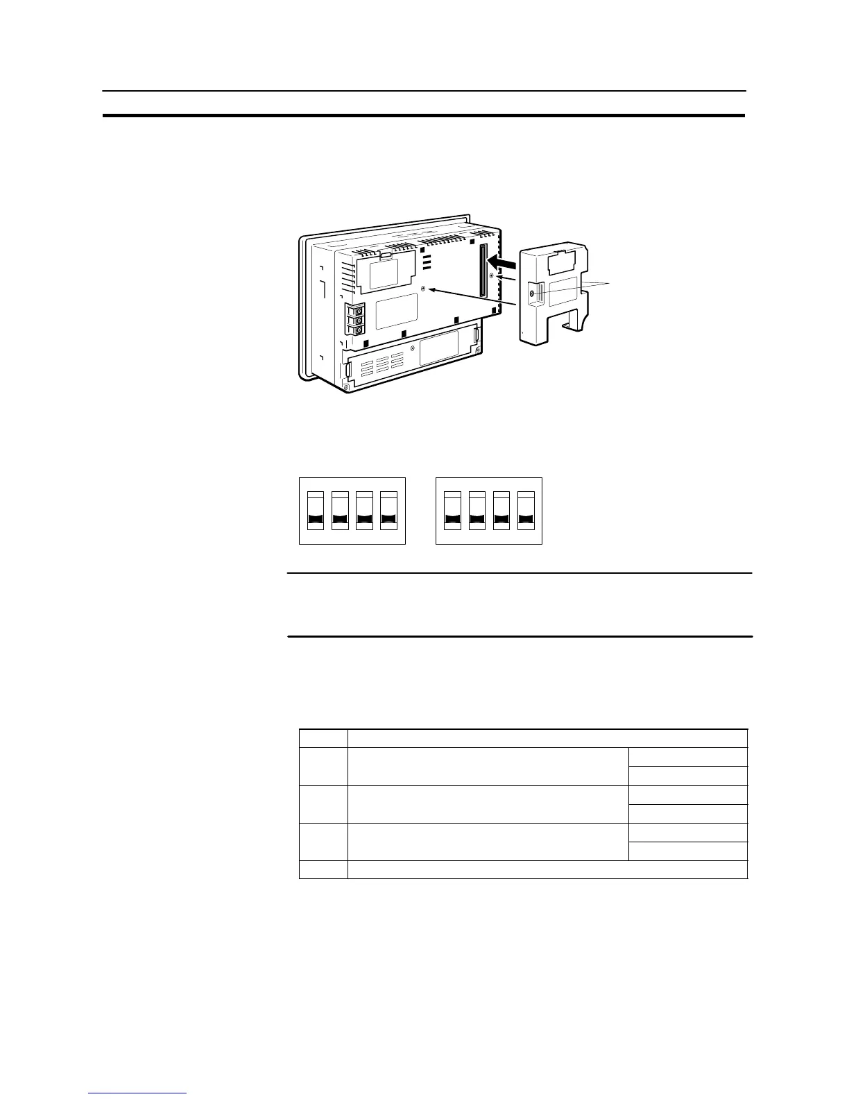
Install the memory unit (NT-MF261) at the expansion interface connector at the
rear of the NT31/NT31C as shown in the figure below. (The expansion interface
connector is located underneath the “note” label.)
Mounting screws
3-6-2 Method of Use
As shown in the figure below, a memory unit has two sets of four DIP switches, and
the operation is determined by the DIP switches that are set at startup.
OFF
3
SW1 SW2
OFF
4432211
Factory setting is turned all to off.
Note Always confirm that the power to the NT31/NT31C is off before setting the DIP
switches.
- Do not touch the PCB (printed circuit board) directly with bare hands.
DIP Switch Functions
The functions of the DIP switches on the memory unit are indicated in the table
below.
S SW1
Switch Function
Automatic transmission (writing from the memory
OFF: Not executed
SW1-1
Automatic transmission (writing from the memory
unit to the PT)
ON : Executed
Automatic transmission (writing from the PT to the
OFF: Not executed
SW1-2
Automatic transmission (writing from the PT to the
memory unit)
ON : Executed
Manual transmission (Direction of transmission and
OFF: Not executed
SW1-3
Manual transmission (Direction of transmission and
bank used selected at the PT touch panel)
ON : Executed
SW1-4 Reserved for system use (must be set to “OFF”)