7
5
3
1
8
6
4
2
658
Using an RS-232C/RS-422A Convertor Unit
APPENDIX C
Note S Do not set both SW1-5 and SW1-6 ON at the same time. This may damage inter-
nal circuits.
S The power supply to the device supplying +5 V must be turned OFF before start-
ing wiring work.
S Before connecting the RS-232C cable and turning on the power to an RS-232C
device such as a PT (i.e., turning on the power to the convertor unit), check that
the cable is wired correctly and that the DIP switch settings are correct. If the
power is turned on while there is a wiring fault, the internal circuits of the conver-
tor unit or the RS-232C device may be damaged.
S When the convertor unit is connected to a C200HX/HG/HE (-ZE) model of OM-
RON PC as an RS-422A device, set DIP switches SW1-5 and SW1-6 as indi-
cated below.
56
SW1-5
OFF
SW1-6
ON
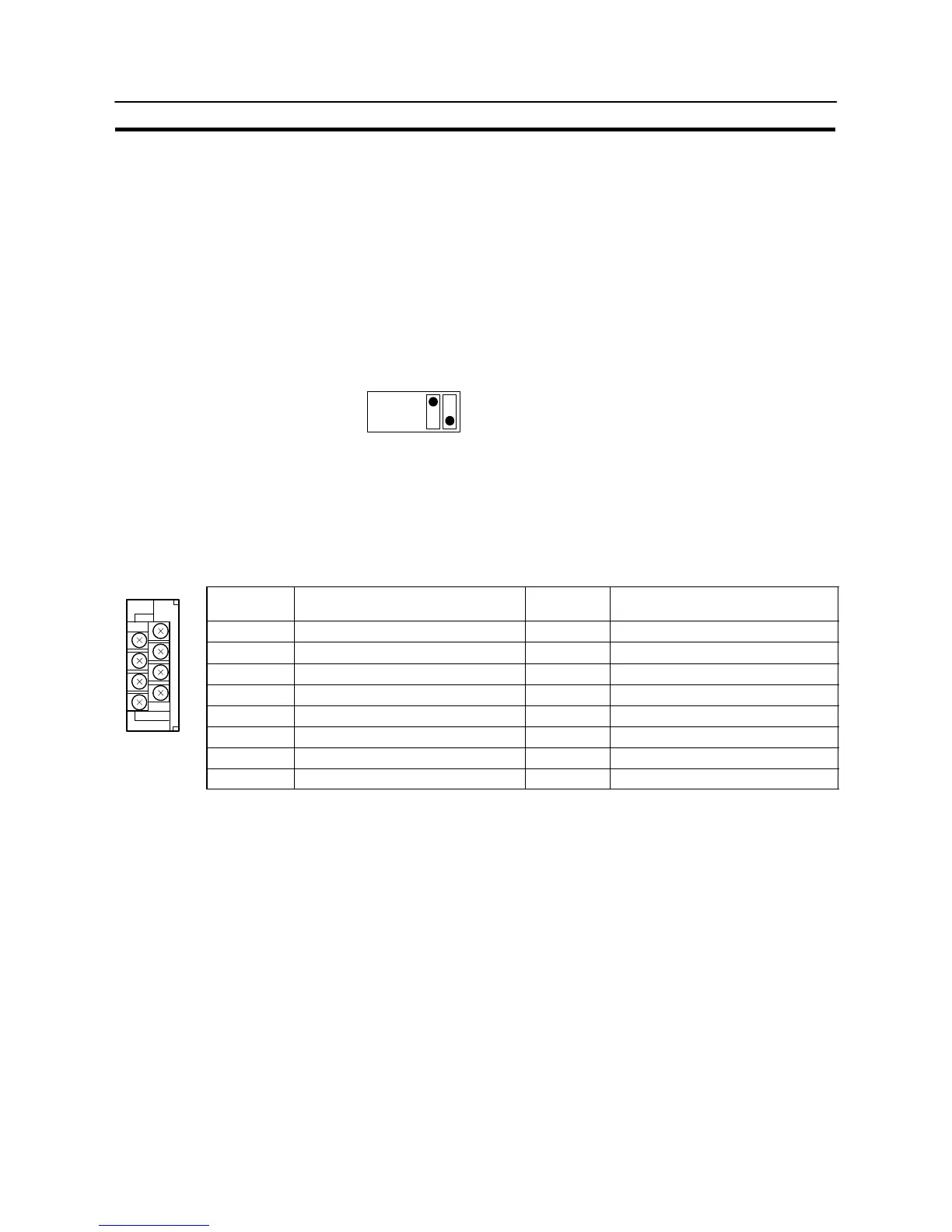
Pin Arrangement
The convertor unit has a terminal block for an RS-422A/485 interface connection and a connector for an RS-232C
interface connection.
The pin arrangements for the RS-422A/485 terminal block and the RS-232C connector are as follows.
RS-422A/485 Terminal Block
Terminal
block pin No.
Signal name Abbreviation
Signal direction
(convertor unit ⇔ RS-422 device)
8 Request to send (−) CSA →
7 Request to send (+) CSB →
6 Receive data (−) RDA ←
5 Receive data (+) RDB ←
4 Send data (−) SDA →
3 Send data (+) SDB →
2 Signal ground SG (GND) –
1 Functional ground –
* The CSB and CSA signals are for specialized applications.

 Loading...


