103
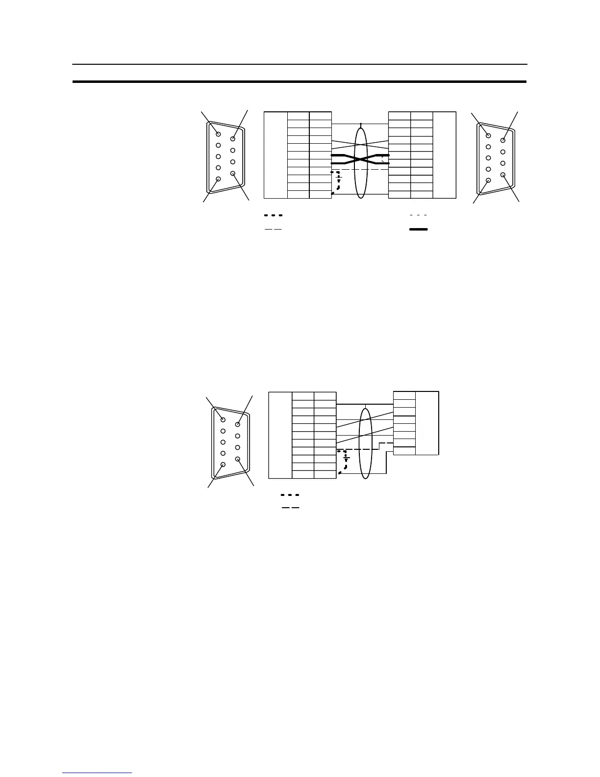
Connecting to the Host’s RS-232C Port
Section 5-1
Shielding wire
Abbreviation
FG
−
SD
RD
RS
CS
+5V
−
−
SG
Pin number
Connector
hood
1
2
3
4
5
6
7
8
9
(9-pin type)
NT-AL001 side PC side
RS-232C
connector
RS-232C
connector
Pin number
Connector
hood
1
2
3
4
5
6
7
8
9
Abbreviation
FG
−
SD
RD
RS
CS
(+5V)
−
−
SG
(9-pin type)
1
6
5
9
1
6
5
9
When there is no +5 V output at the PC side
When there is +5 V output at the PC side
When using host link or NT link (1:1)
When using NT link (1:N)
- When using the host link or NT link (1:1) method, short the RS and CS termi-
nals at the PC side with each other (leave the RS and CS terminals at the NT-
AL001 side open).
- When using the NT link (1:N), cross-connect the RS and CS terminals at the
NT-AL001 and PC sides.
If there is +5 V output at the PC side, no external power supply is required for
the NT-AL001.
Wiring for a Memory Link connection
Prepare the adapter cable while referring to the diagram shown below.
(9–pin type) Shielding wire
No +5 V output is at the host side
A +5 V output is present at the host side
NT-AL001 side
Host side
1
6
5
9
Abbreviation
FG
−
SD
RD
RS
CS
+5V
−
−
SG
Pin number
Connector
hood
1
2
3
4
5
6
7
8
9
RS-232C
connector
RS-232C
connector
Abbreviation
Connector
hood
SD
RD
RS
CS
(+5V)
SG
Since it is necessary to input a voltage of +5 V to the number 6 pin of NT–AL001,
supplying a voltage of 5 V from the host or an external voltage supply for NT–
AL001 is required.