109
Connecting to the Host’s RS-232C Port
Section 5-1
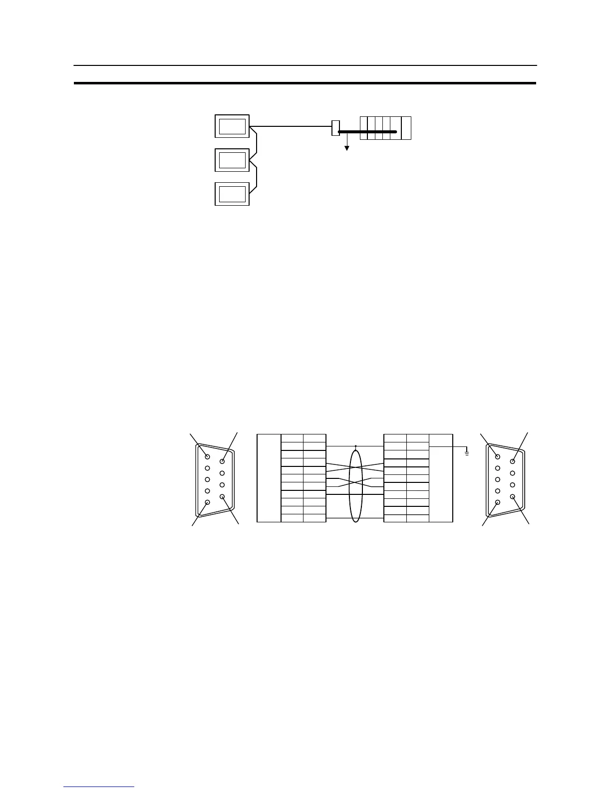
Connecting an NT-AL001 and Host
RS-232C
NT31/NT31C
Host
NT-AL001
Wiring when connecting a CS1 series CS1G/H serial communication board, C
series C200HX/HG/HE (–Z) communication board.
Applicable units:
CS1G-CPU42-E CS1G-CPU43-E
CS1G-CPU44-E CS1G-CPU45-E
CS1H-CPU63-E CS1H-CPU64-E
CS1H-CPU65-E CS1H-CPU66-E
CS1H-CPU67-E
C200HE-CPU32-(Z)E C200HE-CPU42-(Z)E
C200HG-CPU33-(Z)E C200HG-CPU43-(Z)E
C200HG-CPU53-(Z)E C200HG-CPU63-(Z)E
C200HX-CPU34-(Z)E C200HX-CPU44-(Z)E
C200HX-CPU54-(Z)E C200HX-CPU64-(Z)E
C200HX-CPU65-ZE C200HX-CPU85-ZE
6
5
9
1
6
5
9
1
Shielding wire
Abbreviation
FG
−
SD
RD
RS
CS
+5V
−
−
SG
Pin number
Connector
hood
1
2
3
4
5
6
7
8
9
(9-pin type)
NT-AL001 side PC side
RS-232C
connector
RS-232C
connector
Pin number
Connector
hood
1
2
3
4
5
6
7
8
9
Abbreviation
FG
−
SD
RD
RS
CS
+5V
−
−
SG
(9-pin type)
Since the C200HX/HG/HE(-ZE) has a +5 V output, no external power supply is
required CS1G/H and for the NT-AL001.