126
Connecting to the Host’s RS-422A/485 Port
Section 5-2
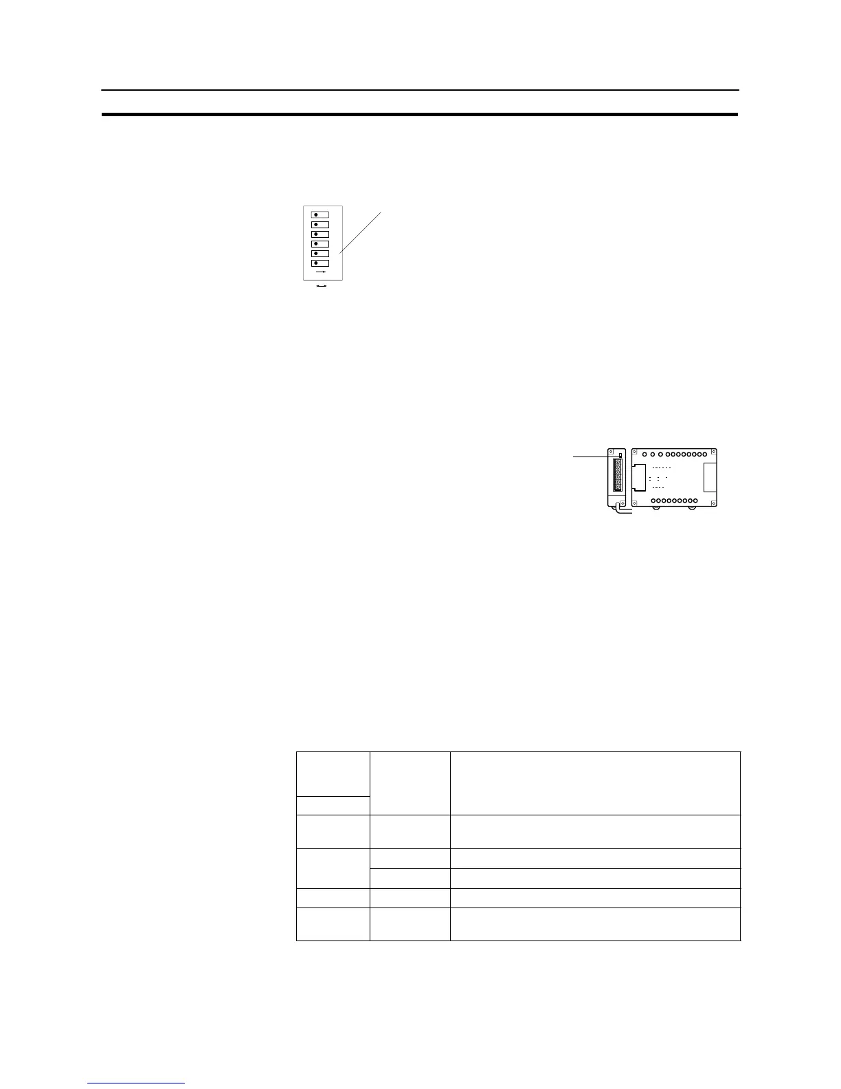
[Setting the DIP switches on the front of a C200HX/HG/HE(-ZE)]
When using a C200HX/HG/HE(-ZE) , the DIP switches on the front panel must
be set as shown below in order to make the settings in the PC system setting
area (data memory) effective.
OFF ON
1
2
3
4
5
6
ON
RS-232C port communication condition setting
Set DIP SW5 to “OFF” to make the settings made in PC system setting
effective.
[Setting switches on a C200HX/HG/HE(-ZE) communication board]
Set the switches on a C200HX/HG/HE(-ZE) communication board as follows.
Switch 1: Set to [4] (4-wire type, for RS-422A)
Switch 2 : Set to “ON” for terminator ON (termination resistance applied)
[Setting the switches on a CPM1 RS-422A adapter]
Set the terminator selector switch to “ON” (upper position).
CPM1
CPM1-
CIF11
Connecting to a CS1 series serial communication board
INNER board with RS-422A/485 port equipped for CS1 series CPU Type :
CS1W-SCB41-E (The port 2 is RS-422A/485 port.)
[Allocation DM area settings for CPU]
Settings are written from the peripheral tool (a programming console or CX-Pro-
grammer) directly into the allocation DM area (system setting area) of the CPU.
After the settings are written, they become effective by turning the power ON,
restarting the unit, restarting the communication port, or executing the STUP
command.
In the following, the channel numbers of the allocation DM area and the settings
are shown.
Allocation
DM area
(CH)
Writing Value Settings
Port 2
DM32010 8000
Host link mode, 2 stop bits,
data length 7 bits, even parity,
DM32011 0000
Communication speed 9600 bps.
0007
Communication speed 19200 bps.
DM32012 0000
Transmit delay time 0 ms.
DM32013 0000
No CTS control
Unit No.0 for host link